HYDROSTATIC LOCKED ENGINE
When an engine is suspected to be hydrostatically
locked, regardless of what caused the problem, the
following steps should be used.
CAUTION: DO NOT use starter motor to rotate the
engine, severe damage may occur.
(1) Inspect air cleaner, induction system and
intake manifold to insure system is dry and clear of
foreign material.
(2) Remove negative battery cable.
(3) Place a shop towel around the spark plugs
when removing them from the engine. This will catch
any fluid that may possibly be in the cylinder under
pressure.
(4) With all spark plugs removed, rotate engine
crankshaft using a breaker bar and socket.
(5) Identify the fluid in the cylinder(s) (i.e., cool-
ant, fuel, oil or other).
(6) Make sure all fluid has been removed from the
cylinders. Inspect engine for damage (i.e., connecting
rods, pistons, valves, etc.)
(7) Repair engine or components as necessary to
prevent this problem from re-occurring.
CAUTION: Squirt approximately one teaspoon of oil
into the cylinders, rotate engine to lubricate the cyl-
inder walls to prevent damage on restart.
(8) Install new spark plugs.
(9) Drain engine oil and remove oil filter.
(10) Fill engine with specified amount of approved
oil and install new oil filter.
(11) Connect negative battery cable.
(12) Start engine and check for any leaks.
LASH ADJUSTER—BLEEDING
Use this procedure to manually bleed aerated oil
from the lash adjuster and remove sponginess.
(1) Run the engine, bringing it to operating tem-
perature in order to freshly pressurize and warm the
valvetrain system oil supply.
(2) Remove cylinder head cover(s).
(3) Ensure the rocker arm is positioned on the
base circle of the cam (Fig. 19). Rotate engine as nec-
essary.
(4) For intake rocker arm positions:
(a) Adjust Special Tool 8351 Release Probe’s
gauge pin to extend approximately 20 mm (0.787
in.). Then, carefully insert the release probe gauge
pin into the lash adjuster service access hole (Fig.
20).
CAUTION: If probe tip breaks off within the lash
adjuster, replace the affected rocker arm.
(b) Gently unseat lash adjuster’s internal check
ball.
(c) While the internal check ball is held
unseated, press the rocker arm into the valve tip,
allowing the lash adjuster to fully collapse. Hold
this fully collapsed position for about one second,
or longer.
(d) Slowly release the rocker arm, thereby
allowing the lash adjuster to extend, which in turn
refills the high pressure chamber with non-aerated
oil.
(e) Remove probe to allow check ball to seat.
(f) Recheck for sponginess. If the lash adjuster
sponginess is not completely or nearly eliminated,
then repeat procedure.
(g) If the spongy condition cannot be removed,
replace effected rocker arm(s).
(5) For exhaust rocker arm positions:
(a) Adjust Special Tool 8351 Release Probe’s
gauge pin to extend approximately 20 mm (0.787
in.). Then, using two release probes, carefully
insert gauge pins into the lash adjuster service
access holes (Fig. 20).
CAUTION: If probe tip breaks off within the lash
adjuster, replace the affected rocker arm.
(b) Gently unseat BOTH lash adjuster’s internal
check ball at the same time.
(c) While the internal check ball is held
unseated, press the rocker arm into the valve tip,
allowing the lash adjuster to fully collapse. Hold
this fully collapsed position for about one second,
or longer.
(d) Slowly release the rocker arm, thereby allow-
ing the lash adjuster to extend, which in turn
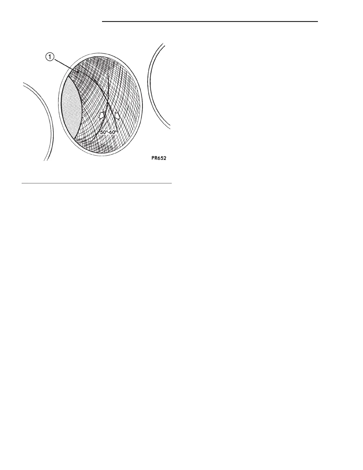
Fig. 18 Cylinder Bore Cross-Hatch Pattern
1 – CROSS-HATCH PATTERN
9 - 94 3.2/3.5L ENGINE LH
SERVICE PROCEDURES (Continued)

 Loading...


