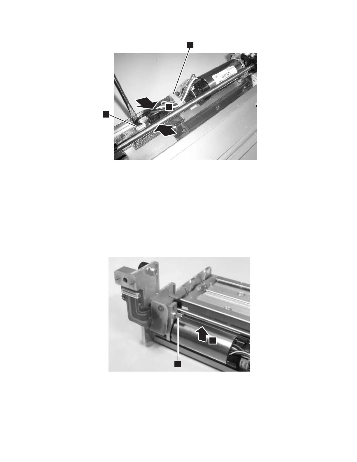
6. Use a small flat blade screw driver to pry up the small white connector (2
in Figure 8-66) gently working the screw driver blade along the entire outside
edge of the connector.
Important: Be very careful not to damage the connector.
7. Disengage the cable retention strap.
8. Using the screwdriver, lift the latch on the black connector then unplug the
cable.
9. Loosen the thumb screw (1 in Figure 8-67).
10. Tilt the Y Motor to the left and remove from the Y-axis/Picker Assembly (2
in Figure 8-67).
a66mi004
1
2
3
Figure 8-66. Y motor connector
a66mi005
1
2
Figure 8-67. Y motor thumb screw
Chapter 8. Add, Check, Adjust, Remove, and Replace Procedures 8-65