Interrupt and trap functions UM0404
104/564 DocID13284 Rev 2
Hardware traps switch the CPU level to maximum priority (15) so no interrupt or PEC
requests will be acknowledged while an exception trap service routine is executed.
Note: The TRAP instruction does not change the CPU level, so software invoked trap service
routines may be interrupted by higher requests.
Interrupt Enable bit IEN globally enables or disables PEC operation and the acceptance of
interrupts by the CPU. When IEN is cleared, no interrupt requests are accepted by the CPU.
When IEN is set to '1', all interrupt sources, which have been individually enabled by the
interrupt enable bit in their associated control registers, are globally enabled.
Note: Traps are non-maskable and are therefore not affected by the IEN bit.
5.2 Operation of the PEC channels
The Peripheral Event Controller (PEC) of the MCU provides eight PEC service channels,
which move a single byte or word between two locations in segment 0 (data pages 3...0).
This is the fastest possible interrupt response and in many cases is sufficient to service the
respective peripheral request (such as from serial channels, or A/D converter). Each
channel is controlled by a dedicated PEC Channel Counter/Control register (PECCx) and a
pair of pointers for source (SRCPx) and destination (DSTPx) of the data transfer. The PECC
registers control the action that is performed by the respective PEC channel.
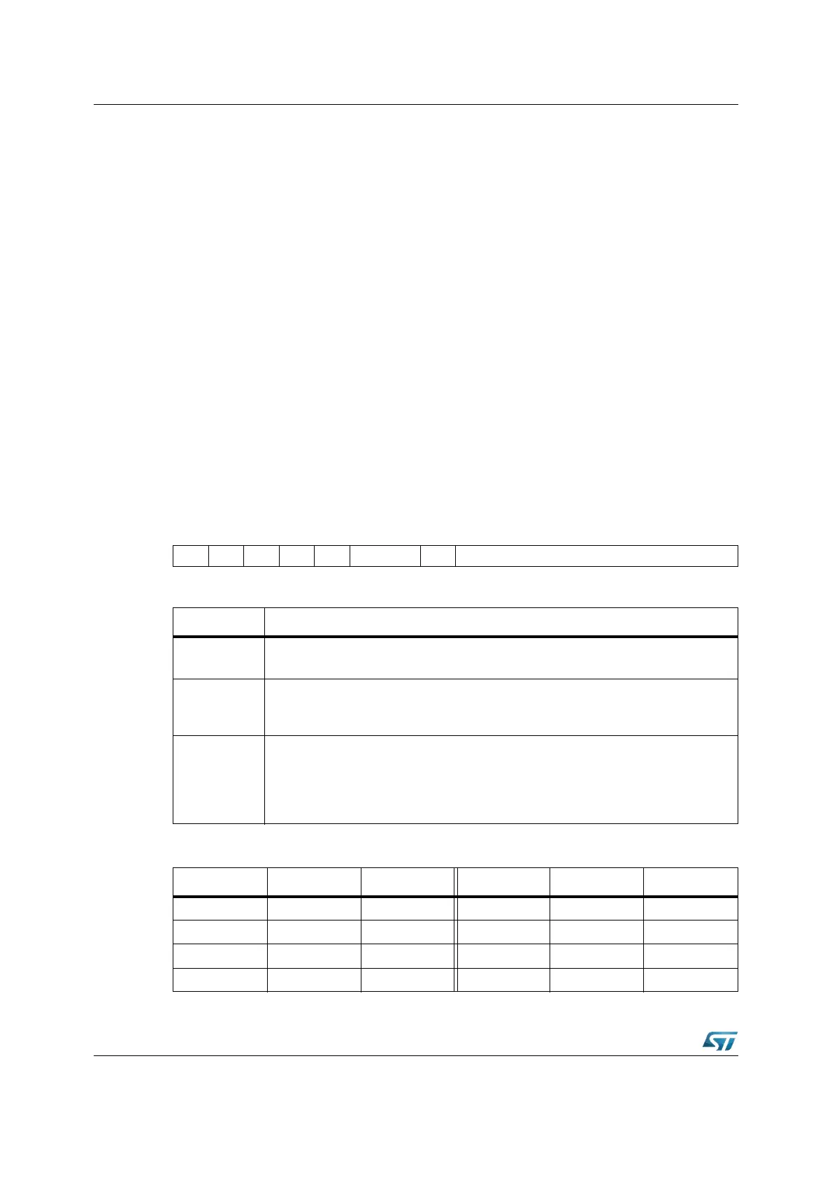
PECCx (FECyh / 6zh, see Table 17) SFR Reset Value: 0000h
1514131211109876543210
----- INCBWT COUNT
RW RW RW
Bit Function
COUNT
PEC Transfer Count
Counts PEC transfers and influences the channel’s action (see table below).
BWT
Byte / Word Transfer Selection
’0’: Transfer a word
’1’: Transfer a byte
INC
Increment Control (Modification of SRCPx or DSTPx)
’00’: Pointers are not modified
’01’: Increment DSTPx by 1 or 2 (BWT)
’10’: Increment SRCPx by 1 or 2 (BWT)
’11’: Reserved. Do not use this combination (changed to ‘10’ by hardware).
Table 17. PEC control register addresses
Register Address Reg. space Register Address Reg. space
PECC0 FEC0h / 60h SFR PECC4 FEC8h / 64h SFR
PECC1 FEC2h / 61h SFR PECC5 FECAh / 65h SFR
PECC2 FEC4h / 62h SFR PECC6 FECCh / 66h SFR
PECC3 FEC6h / 63h SFR PECC7 FECEh / 67h SFR