High-speed synchronous serial interface UM0404
280/564 DocID13284 Rev 2
I/O operation, the respective port latches have to be set to '1', since the port latch outputs
and the alternate output lines are ANDed. When an alternate data output line is not used
(function disabled), it is held at a high level, allowing I/O operations via the port latch. The
direction of the port lines depends on the operating mode. The SSC will automatically use
the correct alternate input or output line of the ports when switching modes. The direction of
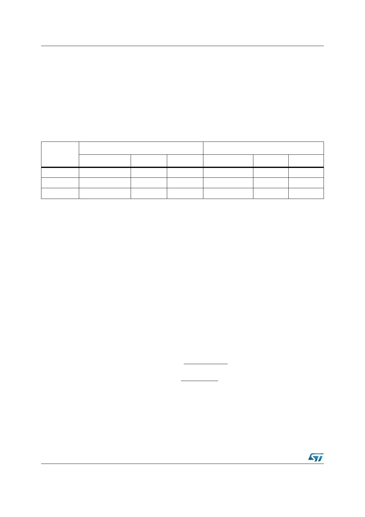
the pins, however, must be programmed by the user, as shown in the tables.
Using the open drain output feature helps to avoid bus contention problems and reduces the
need for hardwired hand-shaking or slave select lines. In this case it is not always
necessary to switch the direction of a port pin. The table below summarizes the required
values for the different modes and pins.
Note: In the table above, an 'x' means that the actual value is irrelevant in the respective mode,
however, it is recommended to set these bits to '1', so they are already in the correct state
when switching between master and slave mode.
12.3 Baud rate generation
The serial channel SSC has its own dedicated 16-bit Baud rate generator with 16-bit reload
capability, allowing Baud rate generation independent from the timers.
The Baud rate generator is clocked by f
CPU
/2. The timer is counting downwards and can be
started or stopped through the global enable bit SSCEN in register SSCCON. Register
SSCBR is the dual-function Baud Rate Generator/Reload register. Reading SSCBR, while
the SSC is enabled, returns the content of the timer. Reading SSCBR, while the SSC is
disabled, returns the programmed reload value. In this mode the desired reload value can
be written to SSCBR.
Note: Never write to SSCBR, while the SSC is enabled.
The formulas below calculate the resulting Baud rate for a given reload value and the
required reload value for a given Baud rate:
(SSCBR) represents the content of the reload register, taken as unsigned 16 bit integer.
Refer to the device datasheet for a table of Baud rates, reload values and resulting bit times.
Pin
Master mode Slave mode
Function Port latch Direction Function Port latch Direction
P3.13 / SCLK Serial Clock Output P3.13 = ‘1’ DP3.13 = ‘1’ Serial Clock Input P3.13 = ‘x’ DP3.13 = ‘0’
P3.9 / MTSR Serial Data Output P3.9
= ‘1’ DP3.9 = ‘1’ Serial Data Input P3.9 = ‘x’ DP3.9 = ‘0’
P3.8 / MRST Serial Data Input P3.8
= ‘x’ DP3.8 = ‘0’ Serial Data Output P3.8 = ‘1’ DP3.8 = ‘1’
Baud rate
SSC
=
f
CPU
2 x [(SSCBR) + 1]
SSCBR = (
f
CPU
2 x Baud rate
SSC
) - 1