DocID13284 Rev 2 163/564
UM0404 Parallel ports
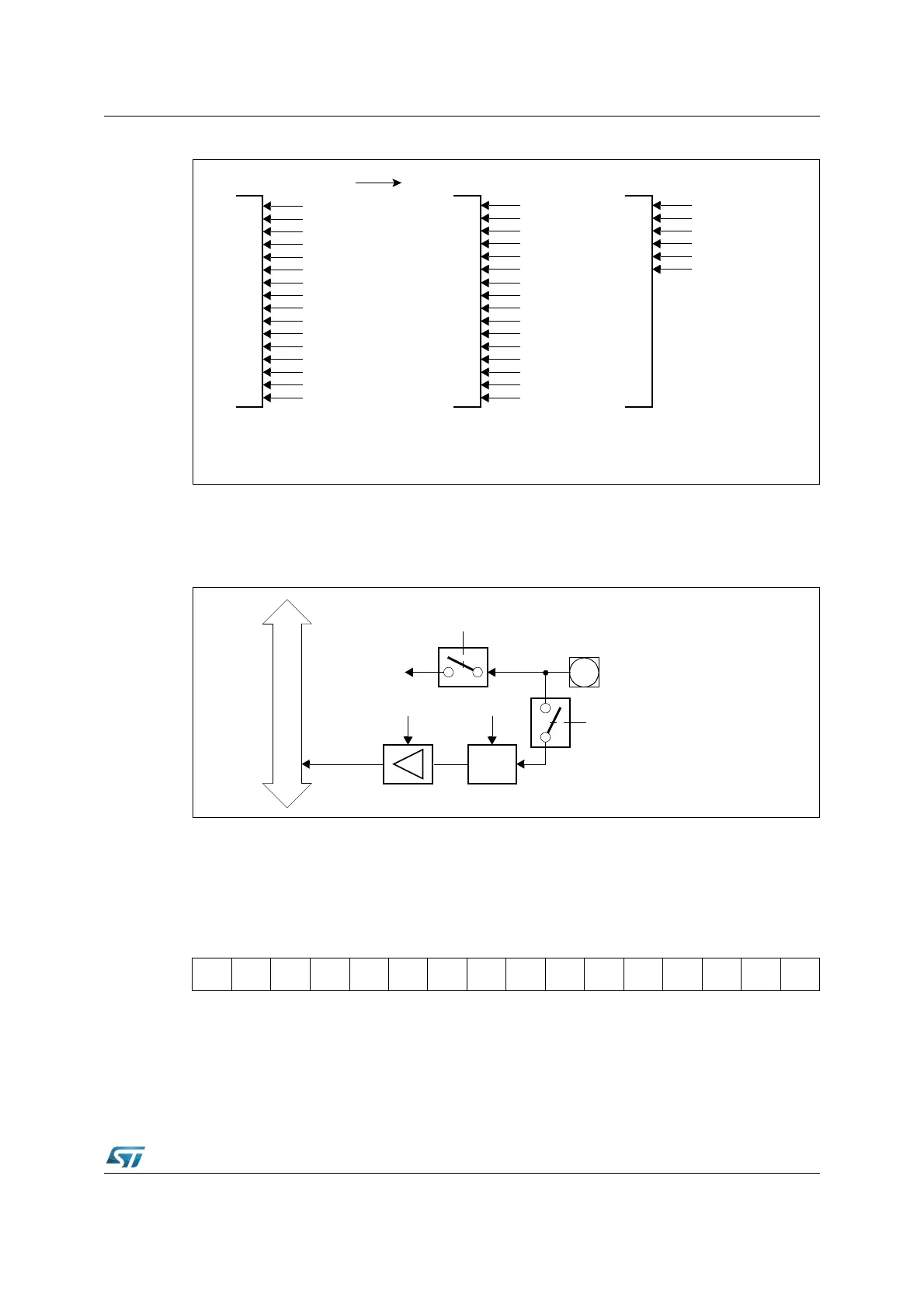
Figure 44. Port5 I/O and alternate functions
Port5 pins have a special port structure (see Figure 45), first because it is an input only port,
and second because the analog input channels are directly connected to the pins rather
than to the input latches.
Figure 45. Block diagram of a Port5 pin
6.7.2 Port5 analog inputs disturb protection
A Schmitt trigger protection can be activated on each pin of Port5 by setting the dedicated
bit of register P5DIDIS.
P5DIDIS (FFA4h / D2h) SFR Reset Value: 0000h
P5.15
P5.14
P5.13
P5.12
P5.11
P5.10
P5.9
P5.8
P5.7
P5.6
P5.5
P5.4
P5.3
P5.2
P5.1
P5.0
Port5
AN15
AN14
AN13
AN12
AN11
AN10
AN9
AN8
AN7
AN6
AN5
AN4
AN3
AN2
AN1
AN0
Alternate Functions a)
General Purpose
Input
T2EUD
T4EUD
T5IN
T6IN
T5EUD
T6EUD
b)
A/D Converter Input Timer Inputs
Read Port P5.y
Internal Bus
Input
Latch
Clock
P5.y/ANy
Read
Buffer
to Sample + Hold
Circuit
Channel
Select
Analog
Switch
y = 15...0
P5DIDIS.y
15 14 13 12 11 10 9 8 7 6 5 4 3 2 1 0
P5DI
DIS.15
P5DI
DIS.14
P5DI
DIS.13
P5DI
DIS.12
P5DI
DIS.11
P5DI
DIS.10
P5DI
DIS.9
P5DI
DIS.8
P5DI
DIS.7
P5DI
DIS.6
P5DI
DIS.5
P5DI
DIS.4
P5DI
DIS.3
P5DI
DIS.2
P5DI
DIS.1
P5DI
DIS.0
RW RW RW RW RW RW RW RW RW RW RW RW RW RW RW RW