Parallel ports UM0404
144/564 DocID13284 Rev 2
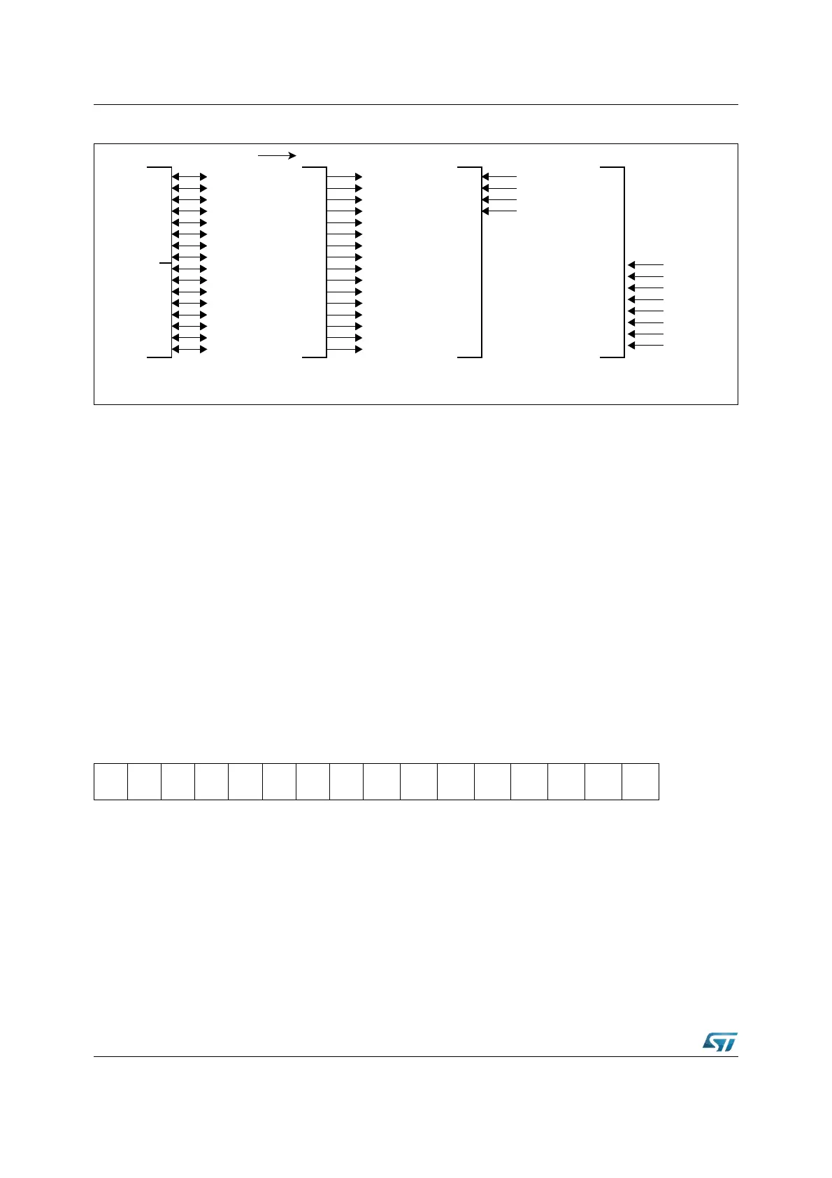
Figure 30. PORT1 I/O and alternate functions
When an external bus mode is enabled, the direction of the port pin and the loading of data
into the port output latch are controlled by the bus controller hardware. The input of the port
output latch is disconnected from the internal bus and is switched to the line labeled
“Alternate Data Output” via a multiplexer. The alternate data is the 16-bit intra-segment
address.
While an external bus mode is enabled, the user software should not write to the port output
latch, otherwise unpredictable results may occur. When the external bus modes are
disabled, the contents of the direction register last written by the user becomes active.
The Figure 32 shows the structure of a PORT1 pin.
6.3.2 PORT1 analog inputs disturb protection
A new register is provided for additional disturb protection support on analog inputs for P1L.
In particular it allows to disable both the digital input and output sections of the I/O structure.
To access this register the bit XMISCEN of register XPERCON and bit XPEN of register
SYSCON must be set. Once a bit of the register is set, the corresponding pin can no longer
be used as general purpose I/O.
XP1DIDIS (EB36h) XBUS Reset Value: 0000h
PORT1
P1H
P1L
Alternate Functions a)
General Purpose
Input/Output
8/16-bit
De-multiplexed
b)
CAPCOM2
Capture Inputs
P1H.7
P1H.6
P1H.5
P1H.4
P1H.3
P1H.2
P1H.1
P1H.0
P1L.7
P1L.6
P1L.5
P1L.4
P1L.3
P1L.2
P1L.1
P1L.0
A15
A14
A13
A12
A11
A10
A9
A8
A7
A6
A5
A4
A3
A2
A1
A0
CC27I
CC26I
CC25I
CC24I
c)
AN23
AN22
AN21
AN20
AN19
AN18
AN17
AN16
ADC
1514131211109876543210
--------
XP1DI
DIS.7
XP1DI
DIS.6
XP1DI
DIS.5
XP1DI
DIS.4
XP1DI
DIS.3
XP1DI
DIS.2
XP1DI
DIS.1
XP1DI
DIS.0
RW RW RW RW RW RW RW RW