The capture / compare units UM0404
336/564 DocID13284 Rev 2
16.4 Capture mode
In response to an external event the content of the associated timer (T0 / T1 or T7 / T8,
depending on the used CAPCOM unit and the state of the allocation control bit ACCx) is
latched into the respective capture register CCx. The external event causing a capture can
be programmed to be either a positive, a negative, or both a positive or a negative transition
at the respective external input pin CCxIO.
The triggering transition is selected by the mode bit CCMODx in the respective CAPCOM
mode control register. In any case, the event causing a capture will also set the respective
interrupt request flag CCxIR, which can cause an interrupt or a PEC service request, when
enabled (see Figure 137).
In order to use the respective port pin as an external capture input pin CCxIO for capture
register CCx, this port pin must be configured as input, the corresponding direction control
bit by setting to ‘0’. To ensure that a signal transition is properly recognized, an external
capture input signal should be held for at least eight CPU clock cycles before it changes its
level.
During these eight CPU clock cycles the capture input signals are scanned sequentially.
When a timer is modified or incremented during this process, the new timer contents will
already be captured for the remaining capture registers within the current scanning
sequence. If pin CCxIO is configured as output, the capture function may be triggered by
modifying the corresponding port output latch via software, like for testing purposes.
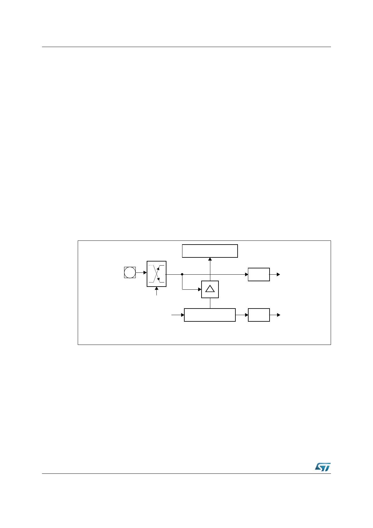
Figure 137. Capture mode block diagram
16.5 Compare modes
The compare modes allow triggering of events (interrupts and / or output signal transitions)
with minimum software overhead.
In all compare modes, the 16 bit value stored in compare register CCx (in the following also
referred to as 'compare value') is continuously compared with the contents of the allocated
timer (T0 / T1 or T7 / T8). If the current timer contents match the compare value, an
appropriate output signal, which is based on the selected compare mode, can be generated
at the corresponding output pin CCxIO (except for CC24IO...CC27IO) and the associated
interrupt request flag CCxIR is set, which can generate an interrupt request (if enabled).
CCMODx
Edge
Select
CCxIO
Capture Register CCx
CAPCOM Timer Ty
TyIR
Interrupt
Request
Input
Clock
x = 31...0
y = 0, 1, 7, 8
CCxIR
Interrupt
Request