XBUS high-speed synchronous serial interface UM0404
294/564 DocID13284 Rev 2
Continuous transfers
When the transmit interrupt request flag is set, it indicates that the transmit buffer XSSCTB
is empty and ready to be loaded with the next transmit data. If XSSCTB has been reloaded
by the time the current transmission is finished, the data is immediately transferred to the
shift register and the next transmission will start without any additional delay. On the data
line there is no gap between the two successive frames, so two bytes transfers would look
the same as one word transfer. This feature can be used to interface with devices which can
operate with or require more than 16 data bits per transfer. It is just a matter of software,
how long a total data frame length can be. This option can also be used to interface to byte
wide and word wide devices on the same serial bus.
Note: Of course, this can only happen in multiples of the selected basic data width, since it would
require disabling/enabling of the XSSC to reprogram the basic data width on-the-fly.
13.2.1 Port control
The XSSC uses three pins of Port6 to communicate with the external world. Pin
P6.5/SCLK1 serves as the clock line, while pins P6.7/MRST1 (Master Receive / Slave
Transmit) and P6.6/MTSR1 (Master Transmit / Slave Receive) serve as the serial data
input/output lines. The operation of these pins depends on the selected operating mode
(master or slave). In order to enable the alternate output functions of these pins instead of
the general purpose I/O operation, the respective port latches have to be set to '1', since the
port latch outputs and the alternate output lines are ANDed. When an alternate data output
line is not used (function disabled), it is held at a high level, allowing I/O operations via the
port latch. The direction of the port lines depends on the operating mode. The XSSC will
automatically use the correct alternate input or output line of the ports when switching
modes. The direction of the pins, however, must be programmed by the user, as shown in
the next table (the table reports the indication of bit names inside XSSCPORT register).
Using the open drain output feature helps to avoid bus contention problems and reduces the
need for hard-wired hand-shaking or slave select lines. In this case it is not always
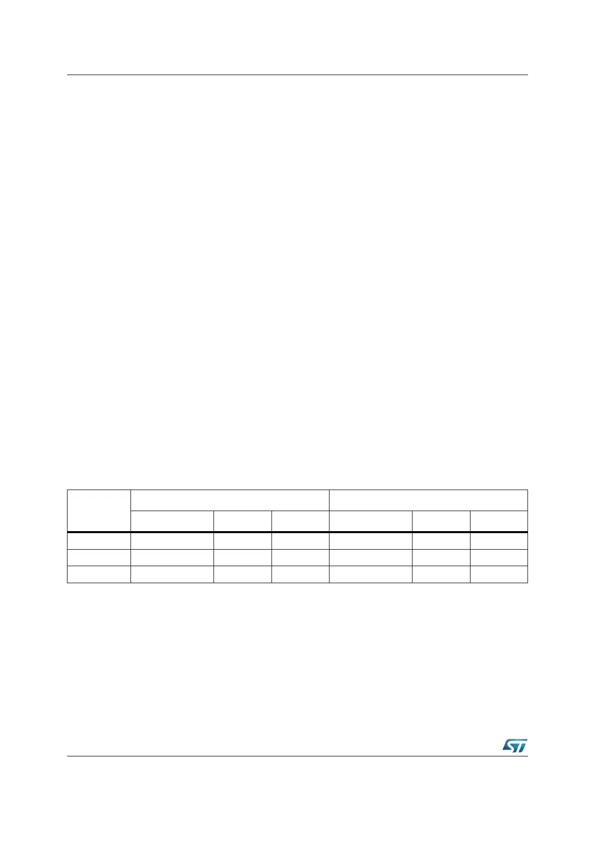
necessary to switch the direction of a port pin. The table below summarizes the required
values for the different modes and pins.
Note: In the table above, an 'x' means that the actual value is irrelevant in the respective mode,
however, it is recommended to set these bits to '1', so they are already in the correct state
when switching between master and slave mode.
13.3 Baud rate generation
The serial channel XSSC has its own dedicated 16-bit Baud rate generator with 16-bit
reload capability, allowing Baud rate generation independent from the timers.
Pin
Master mode Slave mode
Function Port latch Direction Function Port latch Direction
P6.5 / SCLK1 Serial Clock Output XP6.5 = ‘1’ XDP6.5 = ‘1’ Serial Clock Input XP6.5 = ‘x’ XDP6.5 = ‘0’
P6.6 / MTSR1 Serial Data Output XP6.6
= ‘1’ XDP6.6 = ‘1’ Serial Data Input XP6.6 = ‘x’ XDP6.6 = ‘0’
P6.7 / MRST1 Serial Data Input XP6.7
= ‘x’ XDP6.7 = ‘0’ Serial Data Output XP6.7 = ‘1’ XDP6.7 = ‘1’