The capture / compare units UM0404
330/564 DocID13284 Rev 2
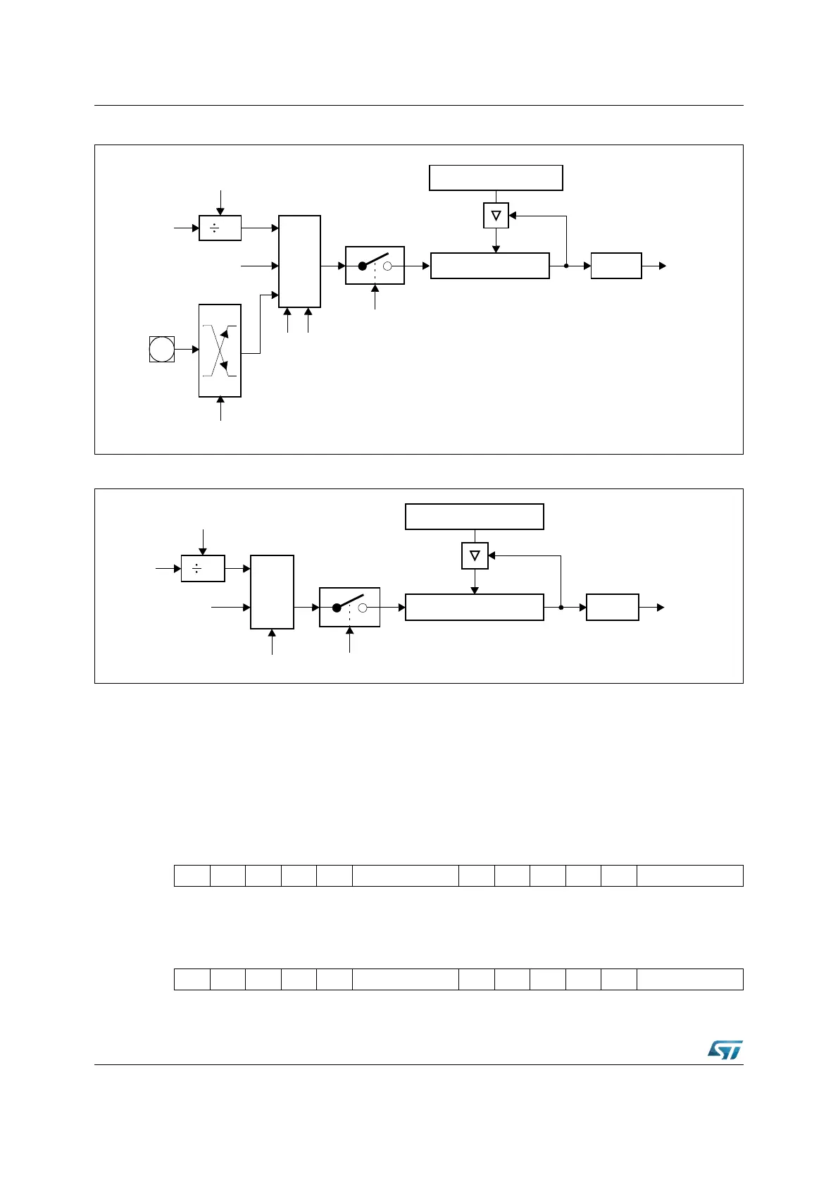
Figure 135. Block diagram of CAPCOM timers T0 and T7
Figure 136. Block diagram of CAPCOM timers T1 and T8
Note: When an external input signal is connected to the input lines of both T0 and T7, these timers
count the input signal synchronously. Thus the two timers can be regarded as one timer
whose contents can be compared with 32 capture registers.
The functions of the CAPCOM timers are controlled via the bit-addressable 16-bit control
registers T01CON and T78CON. The high-byte of T01CON controls T1, the low-byte of
T01CON controls T0, the high-byte of T78CON controls T8, the low-byte of T78CON
controls T7. The control options are identical for all four timers (except for external input).
T01CON (FF50h / A8h) SFR Reset Value: 0000h
T78CON (FF20h / 90h) SFR Reset Value: 0000h
X
Txl
CPU
Clock
TxR
MUX
GPT2 Timer T6
Over / Underflow
Edge Select
TxIN
Txl
Txl TxM
Input
Control
Reload Register TxREL
CAPCOM Timer Tx TxIR
Interrupt
Request
x = 0, 7
X
Txl
CPU
Clock
TxR
MUX
GPT2 Timer T6
Over / Underflow
TxM
Reload Register TxREL
CAPCOM Timer Tx TxIR
Interrupt
Request
x = 1, 8
1514131211109876543210
- T1R - - T1M T1I - T0R - - T0M T0I
RW RW RW RW RW RW
1514131211109876543210
- T8R - - T8M T8I - T7R - - T7M T7I
RW RW RW RW RW RW