Dedicated pins UM0404
180/564 DocID13284 Rev 2
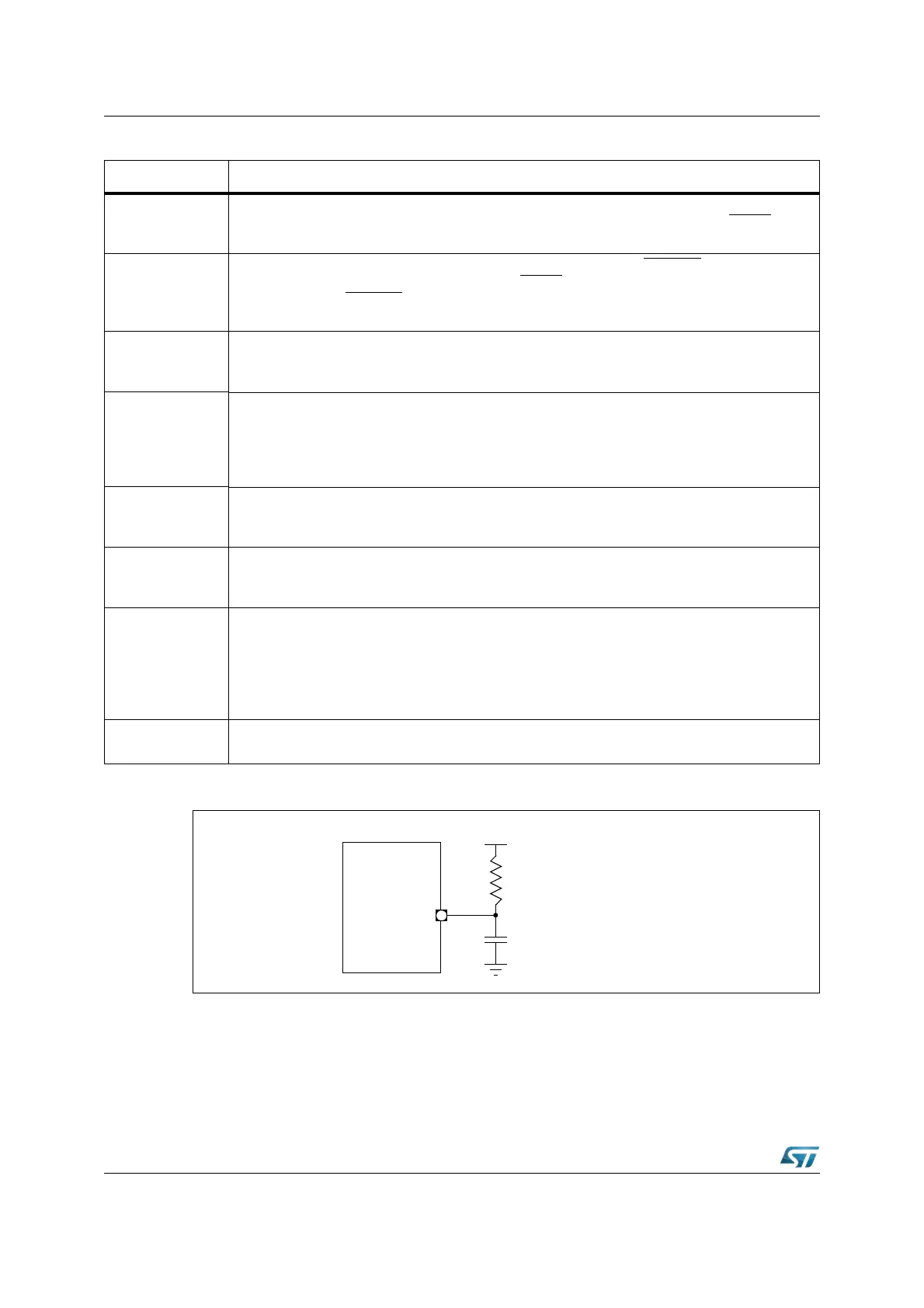
Figure 56. RPD external RC circuit
Note: RPD external RC circuit is used for exiting Power Down mode with external interrupt and for
Power-on with an asynchronous reset.
RSTIN
Reset Input: puts the ST10F276 into the reset default configuration either at Power-On or
external events like a hardware failure or manual reset. The input circuitry of the RSTIN pin
implements an analog filter in order to minimize the noise sensitivity of the reset input.
RSTOUT
Reset Output: provides a special reset signal for external circuitry. RSTOUT
is activated at the
beginning of the reset sequence, triggered via RSTIN
, a watchdog timer overflow or by the
SRST instruction. RSTOUT
remains active (low) until the EINIT instruction is executed. This
allows to initialize the controller before the external circuitry is activated.
XTAL1, XTAL2
Main Oscillator Input/Output: connect the internal clock oscillator to the external crystal. An
external clock signal may be fed to the input XTAL1, leaving XTAL2 open (only when Direct
Drive configuration is selected).
XTAL3, XTAL4
32 kHz Oscillator Input/Output: connect the 32 kHz internal clock oscillator to the external
crystal. When not used, the XTAL3 should be tied to ground to avoid spurious consumption,
while XTAL4 should be left unconnected; besides, bit OFF32 in RTCCON register should be
set. 32 kHz oscillator can only be driven by an external crystal, and not by a different external
clock source.
V
AREF
, V
AGND
ADC Reference Supplies: provide the reference voltage and ground for the Analog to Digital
Converter. Besides, these pins provide also the power supply to analog circuitry of the ADC
module itself.
V
DD
, V
SS
Digital Power Supply and Ground: provide the power supply for the digital logic of the
ST10F276. All V
DD
(8) pins and all V
SS
(9) pins must be connected to the power supply and
ground, respectively.
RPD
Exit from Power Down: If a Fast External Interrupt pin (EX7IN...EX0IN) is used to exit from
Power Down mode, an external RC circuit should be connected to the RPD pin. The
discharging of the external capacitor causes a delay that allows the oscillator and PLL circuits
to stabilize before the clock signal is delivered to the CPU and peripherals (see Figure 56). For
more information on exiting Power Down mode refer to Section 24: Power reduction modes on
page 502.
V
18
1.8V Decoupling pin: a decoupling capacitor must be connected between this pin and nearest
V
SS
pin.
Table 29. Summary of dedicated pins (continued)
Pin(s) Function
RPD
V
DD
C1
R1
200kΩ-1MΩ typical
1µF typical