DocID13284 Rev 2 509/564
UM0404 Power reduction modes
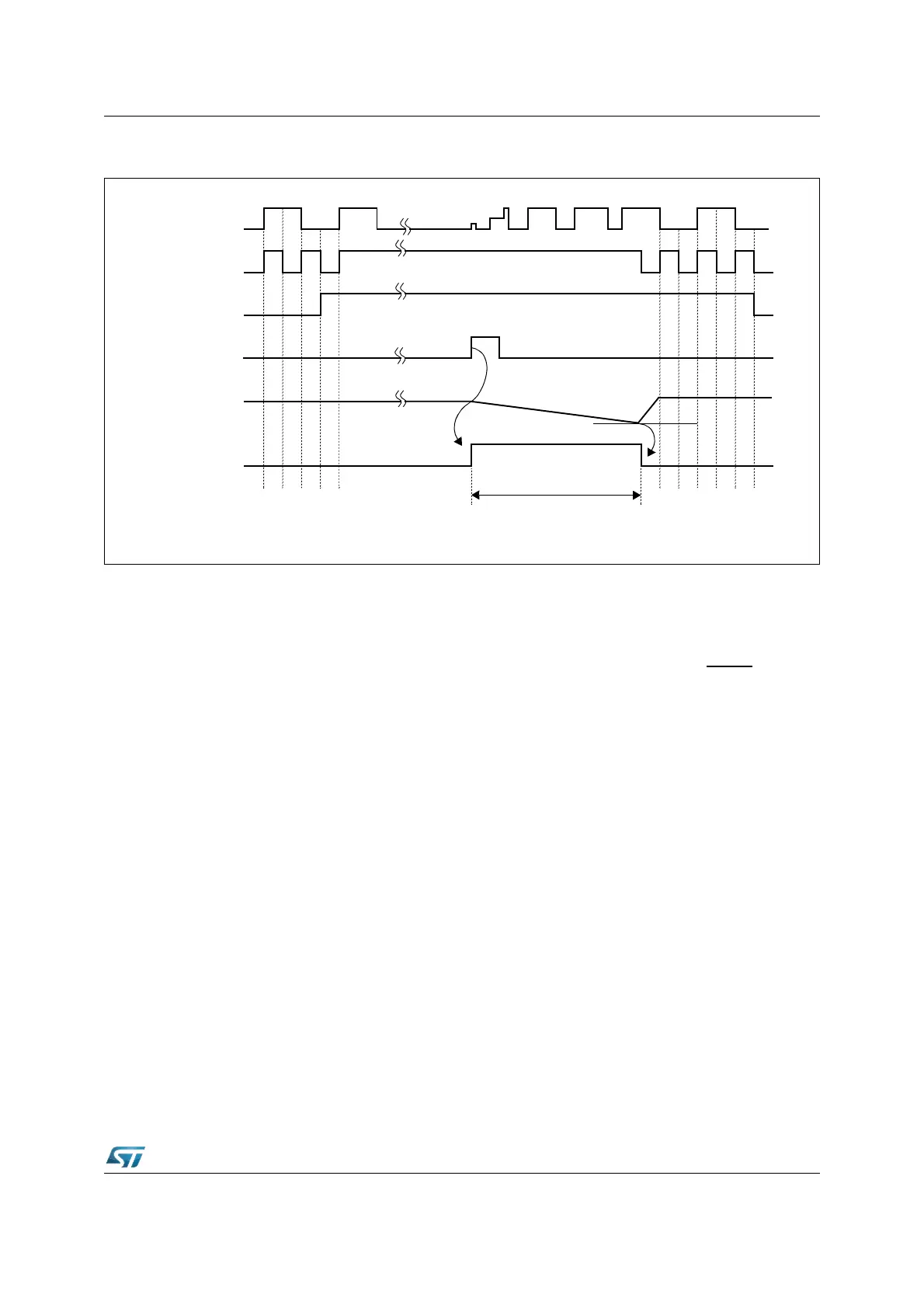
Figure 213. Power down exit sequence using an external interrupt (PLL x 2) real time clock and
power down mode
If the Real Time Clock is running (RTOFF bit of RTCCON register cleared), when PWRDN
instruction is executed, the oscillator circuit which is providing the reference to the counter is
not stopped. The selection of which of the two on-chip oscillator amplifier circuits should
provide the reference clock to the Real Time Clock counter is determined whenever a
Power-On sequence is applied on main V
DD
pins. By default after Power-On, the reference
clock is the main oscillator; immediately after exiting from Power-On reset (RSTIN
pin
released), an internal mechanism is able to detect the presence or absence of a clock signal
from the low-power oscillator (32 kHz, see XTAL3 / XTAL4 pins). In case this oscillator is
running, the reference for the Real Time Clock module becomes the 32 kHz ones (three to
five 32 kHz clock pulses later). On the contrary, if no oscillation is detected on XTAL3 /
XTAL4, the reference for the counter will remain the one from the main on-chip oscillator
(XTAL1 / XTAL2).
Note: 1 In case the switch occurred (32 kHz reference selected), it is possible to come back to the
default configuration either via software by setting the bit OFF32 of RTCCON register or
through a new Power-On sequence.
2 When no external 32 kHz crystal is connected, XTAL3 and XTAL4 pins should be properly
biased to a steady value, to avoid any spike, that would cause an unwanted switching of the
reference clock for the Real Time Clock counter, from the main oscillator (running) signal to
the low-power oscillator (not running, only noisy).
24.3 Stand-by mode
In Stand-by mode, the RAM array is maintained powered through the dedicated pin V
STBY
when ST10F276 main power supply (V
DD
) is turned off.
To enter Stand-by Mode is mandatory to held the device under reset: once the device is
under reset, the RAM is disabled (see XRAM2EN bit of XPERCON register), and its digital
CPU clk
Power Down Signal
External
RPD
ExitPwrd
XTAL1
(Internal)
Interrupt
(Internal)
~ 2.5 V
Delay for oscillator / PLL
stabilization