DocID13284 Rev 2 147/564
UM0404 Parallel ports
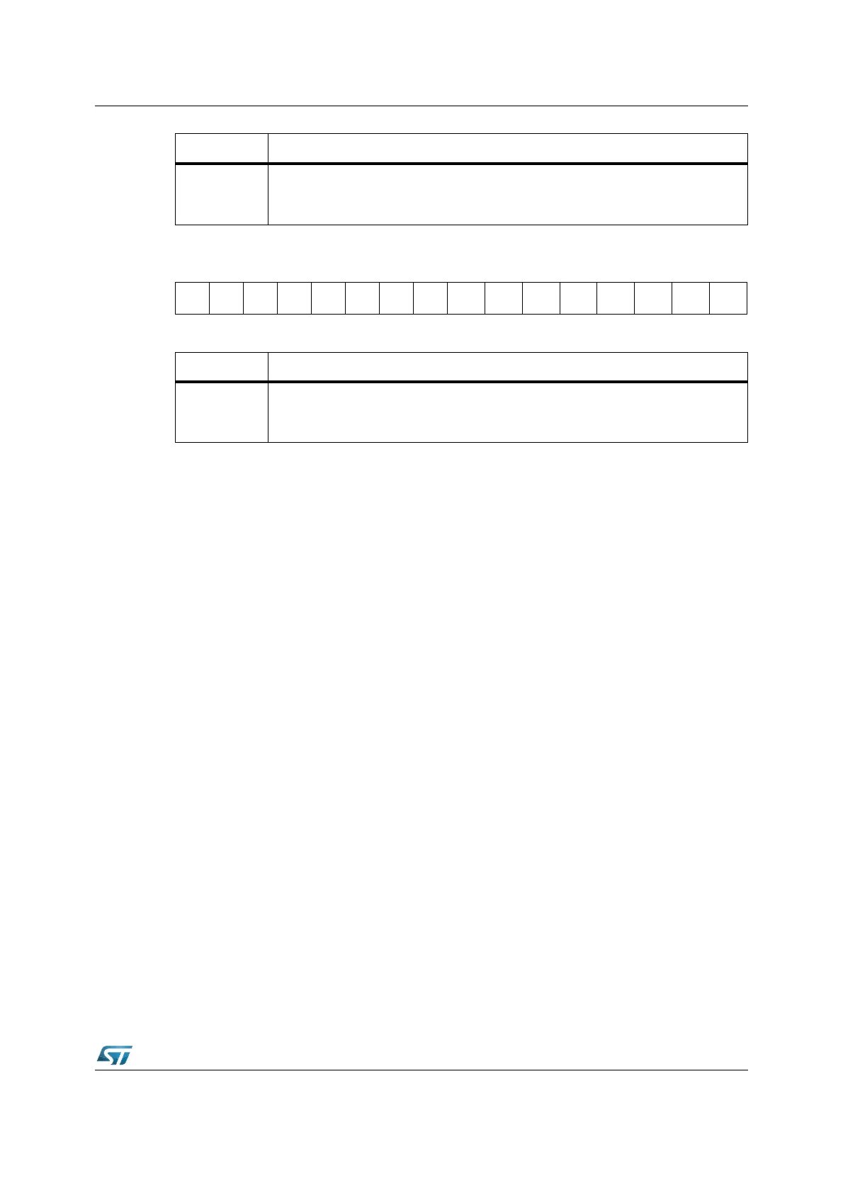
ODP2 (F1C2h / E1h) ESFR Reset Value: 0000h
6.4.1 Alternate functions of Port2
All Port2 lines (P2.15...P2.0) can be configured capture inputs or compare outputs
(CC15IO...CC0IO) for the CAPCOM1 unit.
When a Port2 line is used as a capture input, the state of the input latch, which represents
the state of the port pin, is directed to the CAPCOM unit via the line “Alternate Pin Data
Input”. If an external capture trigger signal is used, the direction of the respective pin must
be set to input. If the direction is set to output, the state of the port output latch will be read
since the pin represents the state of the output latch. This can be used to trigger a capture
event through software by setting or clearing the port latch. Note that in the output
configuration, no external device may drive the pin, otherwise conflicts would occur.
When a Port2 line is used as a compare output (compare modes 1 and 3), the compare
event (or the timer overflow in compare mode 3) directly effects the port output latch. In
compare mode 1, when a valid compare match occurs, the state of the port output latch is
read by the CAPCOM control hardware via the line “Alternate Latch Data Input”, inverted,
and written back to the latch via the line “Alternate Data Output”. The port output latch is
clocked by the signal “Compare Trigger” which is generated by the CAPCOM unit. In
compare mode 3, when a match occurs, the value '1' is written to the port output latch via
the line “Alternate Data Output”. When an overflow of the corresponding timer occurs, a '0' is
written to the port output latch. In both cases, the output latch is clocked by the signal
“Compare Trigger”. The direction of the pin should be set to output by the user, otherwise
the pin will be in the high-impedance state and will not reflect the state of the output latch.
As can be seen from the port structure (Figure 2 on page 24), the user software always has
free access to the port pin even when it is used as a compare output. This is useful for
setting up the initial level of the pin when using compare mode 1 or the double-register
mode. In these modes, unlike in compare mode 3, the pin is not set to a specific value when
a compare match occurs, but is toggled instead.
When the user wants to write to the port pin at the same time a compare trigger tries to clock
the output latch, the write operation of the user software has priority. Each time a CPU write
access to the port output latch occurs, the input multiplexer of the port output latch is
Bit Function
DP2.y
Port direction register DP2 bit y
’0’: Port line P2.y is an input (high-impedance).
’1’: Port line P2.y is an output.
1514131211109876543210
ODP2
.15
ODP2
.14
ODP2
.13
ODP2
.12
ODP2
.11
ODP2
.10
ODP2
.9
ODP2
.8
ODP2
.7
ODP2
.6
ODP2
.5
ODP2
.4
ODP2
.3
ODP2
.2
ODP2
.1
ODP2
.0
RW RW RW RW RW RW RW RW RW RW RW RW RW RW RW RW
Bit Function
ODP2.y
Port Open Drain control register ODP2 bit y
’0’: Port line P2.y output driver in push-pull mode.
’1’: Port line P2.y output driver in open-drain mode.