Parallel ports UM0404
150/564 DocID13284 Rev 2
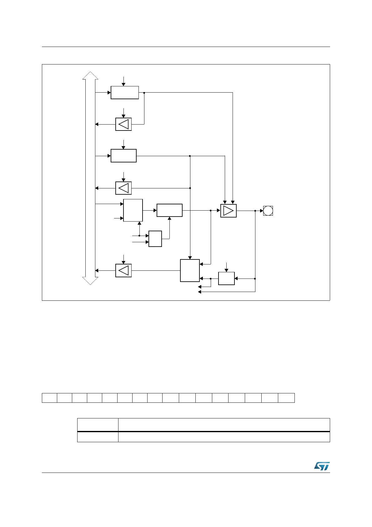
Figure 34. Block diagram of a Port2 pin
6.5 Port3
If this 15 bit port is used for general purpose I/O, the direction of each line can be configured
by the corresponding direction register DP3. Most port lines can be switched into push-pull
or open-drain mode by the open-drain control register ODP3 (pins P3.15 and P3.12 do not
support open drain mode).
Due to pin limitations, register bit P3.14 is not connected to any output pin.
P3 (FFC4h / E2h) SFR Reset Value: 0000h
Open Drain
Latch
Write ODP2.y
Read ODP2.y
Direction
Latch
Write DP2.y
Read DP2.y
Internal Bus
MUX
0
1
Alternate data input
Input
Latch
Clock
P2.y
CCyIO
Output
Buffer
x = 7...0
Alternate
Data
Output
MUX
0
1
Output
Latch
≥ 1
Write Port P2.y
Compare Trigger
Read P2.y
Fast external interrupt input
y = 15...0
EXxIN
1514131211109876543210
P3.15 - P3.13P3.12P3.11P3.10 P3.9 P3.8 P3.7 P3.6 P3.5 P3.4 P3.3 P3.2 P3.1 P3.0
RW RW RW RW RW RW RW RW RW RW RW RW RW RW RW
Bit Function
P3.y Port data register P3 bit y