DocID13284 Rev 2 401/564
UM0404 I
2
C interface
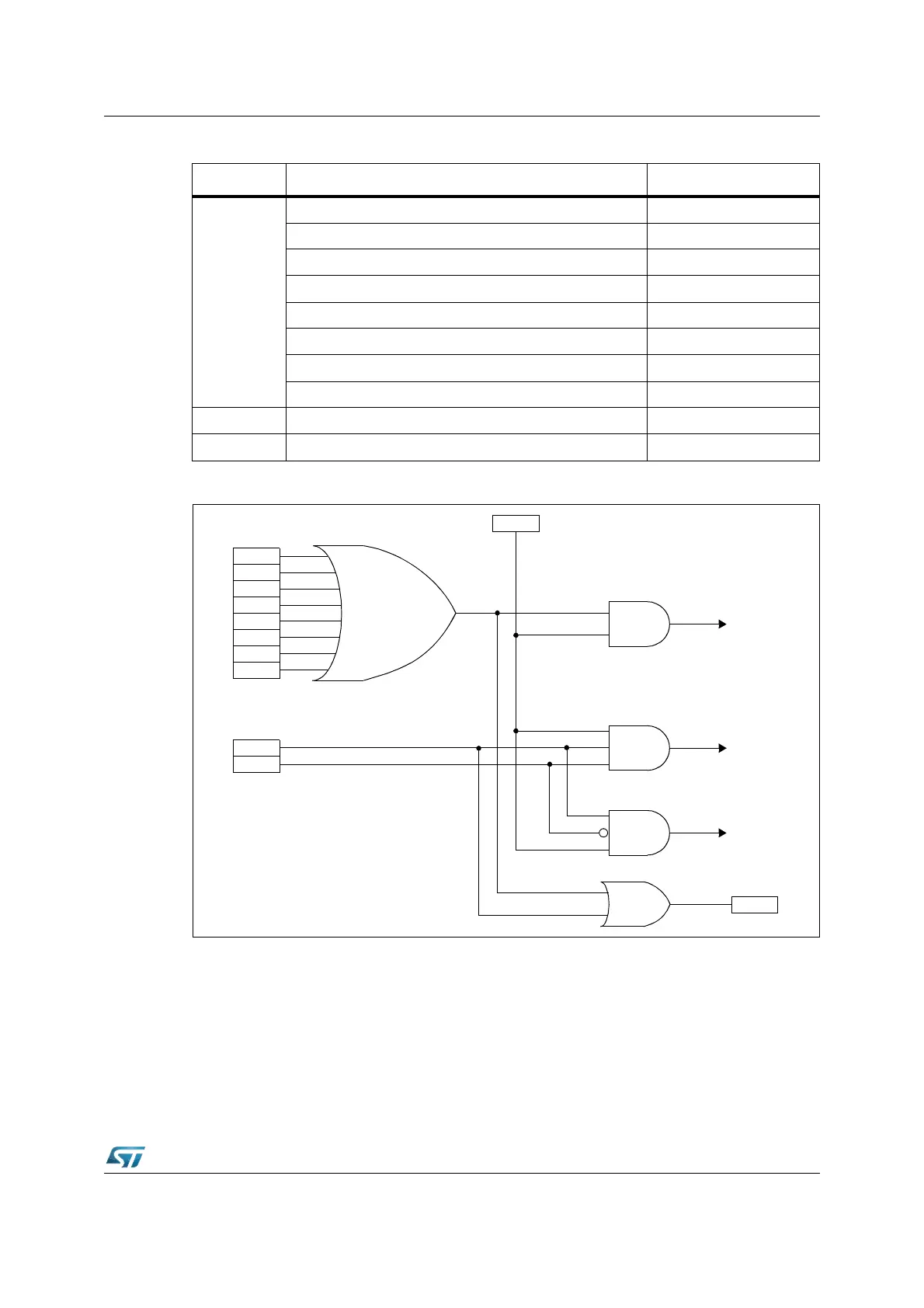
Figure 171. Event flags and interrupt generation
Up to four interrupt control registers (XIRxSEL, x = 0, 1, 2, 3) are provided in order to select
the source of the XBUS interrupt: the transmit interrupt, the receive interrupt and the error
interrupt of I
2
C Interface are linked to the one of the XPxIC registers (x = 0, 1, 2, 3). In
particular, the three interrupt lines are available on the following interrupt vectors:
• Receive XP0INT XP1INT XP2INT
• Transmit XP0INT XP1INT XP2INT
• Error XP3INT
Refer to Section 5.7: X-peripheral interrupt on page 117 for details.
Table 57. Interrupt event summary
Line Interrupt event Event flag
Error
10-bit Address Sent Event (Master mode) ADD10
Start Bit Generation Event (Master mode) SB
Address Matched Event (Slave mode) ADSL
Address Byte Transmission Event (Master Mode) ENDAD
Acknowledge Failure Event AF
Stop Detection Event (Slave mode) STOPF
Arbitration Lost Event (Multi-master configuration) ARLO
Bus Error Event BERR
Transmit Byte Transmission Event BTF with TRA = 1
Receive Byte Reception Event BTF with TRA = 0
Error
SB
ADD10
ENDAD
ADSL
STOPF
AF
BERR
ARLO
BTF
Transmit
TRA
Receive
ITE
EVF