DocID13284 Rev 2 291/564
UM0404 XBUS high-speed synchronous serial interface
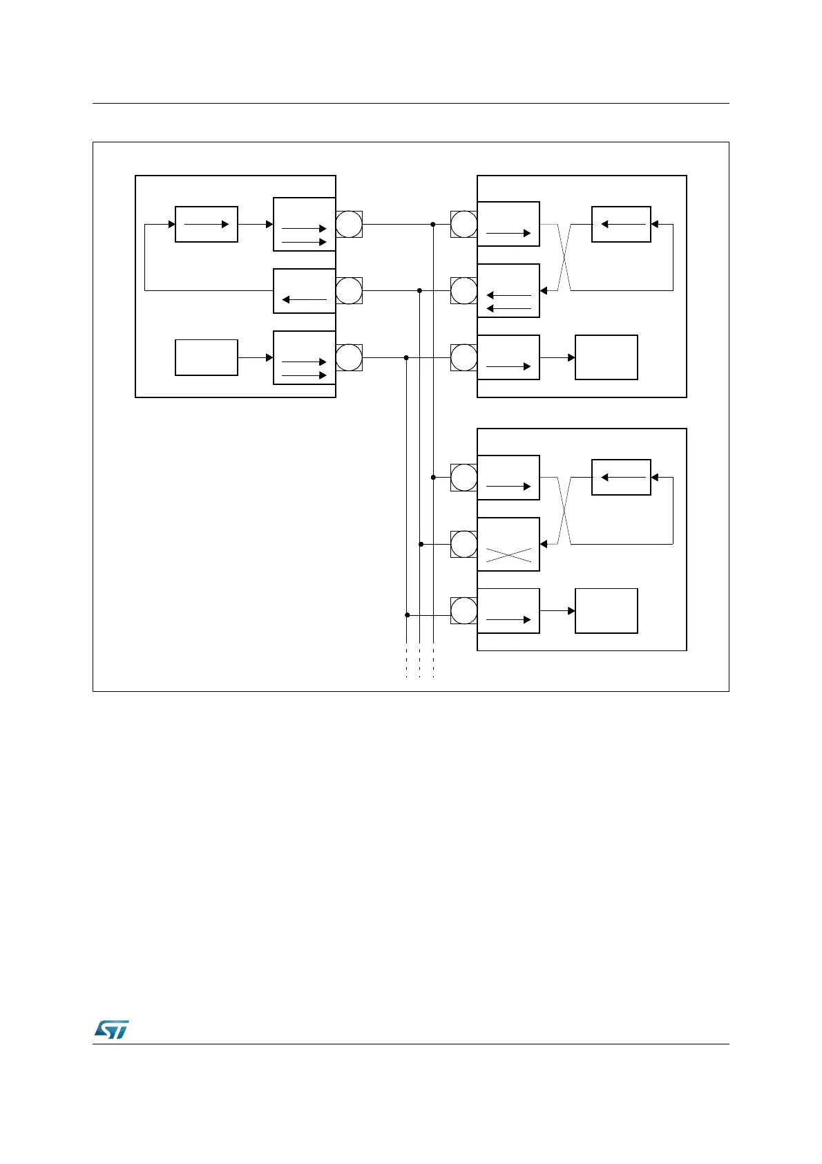
Figure 120. XSSC full duplex configuration
The data output pins MRST1 of all slave devices are connected together onto the one
receive line in this configuration. During a transfer each slave shifts out data from its shift
register. There are two ways to avoid collisions on the receive line due to different slave
data:
Only one slave drives the line: it enables the driver of its MRST1 pin. All the other slaves
have to program there MRST1 pins to input. So only one slave can put its data onto the
master's receive line. Only receiving of data from the master is possible. The master selects
the slave device from which it expects data either by separate select lines, or by sending a
special command to this slave. The selected slave then switches its MRST1 line to output,
until it gets a de-selection signal or command.
The slaves use open drain output on MRST1. This forms a AND-wired connection. The
receive line needs an external pull-up in this case. Corruption of the data on the receive line
sent by the selected slave is avoided, when all slaves which are not selected for
transmission to the master only send ones (‘1’). Since this high level is not actively driven
onto the line, but only held through the pull-up device, the selected slave can pull this line
actively to a low level when transmitting a zero bit. The master selects the slave device from
Shift Register
MTSR1
CLK
MRST1
Clock
Master
Device #1
Transmit
Receive
Clock
MTSR1
MRST1
CLK
Clock
Shift Register
Device #2 Slave
MTSR1
MRST1
CLK
Clock
Shift Register
Device #2 Slave