DocID13284 Rev 2 279/564
UM0404 High-speed synchronous serial interface
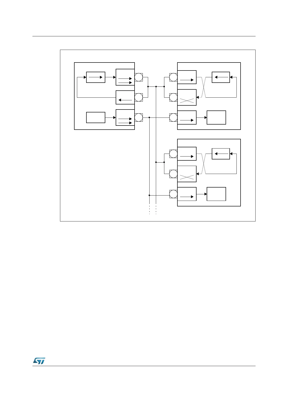
Figure 115. SSC half duplex configuration
Continuous transfers
When the transmit interrupt request flag is set, it indicates that the transmit buffer SSCTB is
empty and ready to be loaded with the next transmit data. If SSCTB has been reloaded by
the time the current transmission is finished, the data is immediately transferred to the shift
register and the next transmission will start without any additional delay. On the data line
there is no gap between the two successive frames, so two bytes transfers would look the
same as one word transfer. This feature can be used to interface with devices which can
operate with or require more than 16 data bits per transfer. It is just a matter of software,
how long a total data frame length can be. This option can also be used to interface to byte
wide and word wide devices on the same serial bus.
Note: Of course, this can only happen in multiples of the selected basic data width, since it would
require disabling/enabling of the SSC to reprogram the basic data width on-the-fly.
12.2.1 Port control
The SSC uses three pins of Port3 to communicate with the external world. Pin P3.13/SCLK
serves as the clock line, while pins P3.8/MRST (Master Receive / Slave Transmit) and
P3.9/MTSR (Master Transmit / Slave Receive) serve as the serial data input/output lines.
The operation of these pins depends on the selected operating mode (master or slave). In
order to enable the alternate output functions of these pins instead of the general purpose
Shift Register
MTSR
CLK
MRST
Clock
Master
Device #1
Clock
MTSR
CLK
Clock
Shift Register
Device #2 Slave
MTSR
MRST
CLK
Clock
Shift Register
Device #3 Slave
MRST
Common
Transmit/
Receive
Line