DocID13284 Rev 2 365/564
UM0404 XBUS pulse width modulation module
This type of comparison allows a flexible control of the PWM signal. For the register
locations refer to Ta ble 53.
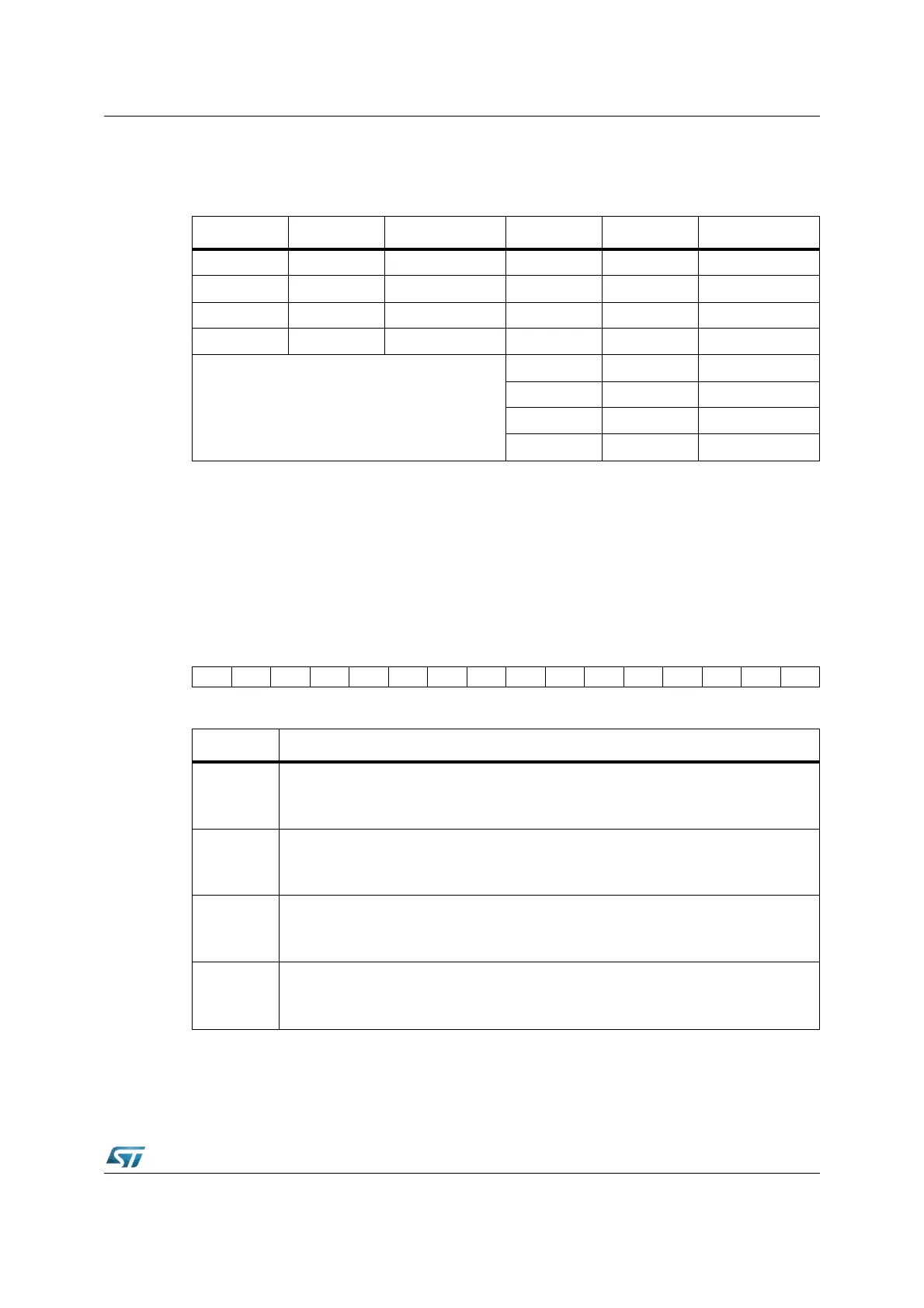
XPWM control register XPWMCON0
Register XPWMCON0 controls the function of the timers of the four XPWM channels and
the channel specific interrupts. Having the control bit organized in functional groups allows
to start or to stop all the four XPWM timers simultaneously with one bit-field instruction.
Note: This register is not bit-addressable; the bit-addressability is available via specific ‘set’ and
‘Clear’ write-only registers XPWMCON0SET and XPWMCON0CLR.
XPWMCON0 (EC00h) XBUS Reset Value: 0000h
Table 55. XPWM module channel specific register addresses
Register Address Reg. space Register Address Reg. space
XPW0 EC30h XBUS XPT0 EC10h XBUS
XPW1 EC32h XBUS XPT1 EC12h XBUS
XPW2 EC34h XBUS XPT2 EC14h XBUS
XPW3 EC36h XBUS XPT3 EC16h XBUS
All XPWM registers are not bit-addressable.
XPP0 EC20h XBUS
XPP1 EC22h XBUS
XPP2 EC24h XBUS
XPP3 EC26h XBUS
15 14 13 12 11 10 9 8 7 6 5 4 3 2 1 0
PIR3 PIR2 PIR1 PIR0 PIE3 PIE2 PIE1 PIE0 PTI3 PTI2 PTI1 PTI0 PTR3 PTR2 PTR1 PTR0
RW RW RW RW RW RW RW RW RW RW RW RW RW RW RW RW
Bit Function
PTRx
XPWM Timer x Run Control bit
‘0’: Timer XPTx is disconnected from its input clock
‘1’: Timer XPTx is running
PTIx
XPWM Timer x Input Clock Selection
‘0’: Timer XPTx clocked with CLK
CPU
‘1’: Timer XPTx clocked with CLK
CPU
/ 64
PIEx
XPWM Channel x Interrupt Enable Flag
‘0’: Interrupt from channel x disabled
‘1’: Interrupt from channel x enabled
PIRx
XPWM Channel x Interrupt Request Flag
‘0’: No interrupt request from channel x
‘1’: Channel x interrupt pending (must be reset via software)