XBUS pulse width modulation module UM0404
366/564 DocID13284 Rev 2
XPWMCON0SET (EC06h) XBUS Reset Value: 0000h
XPWMCON0CLR (EC08h) XBUS Reset Value: 0000h
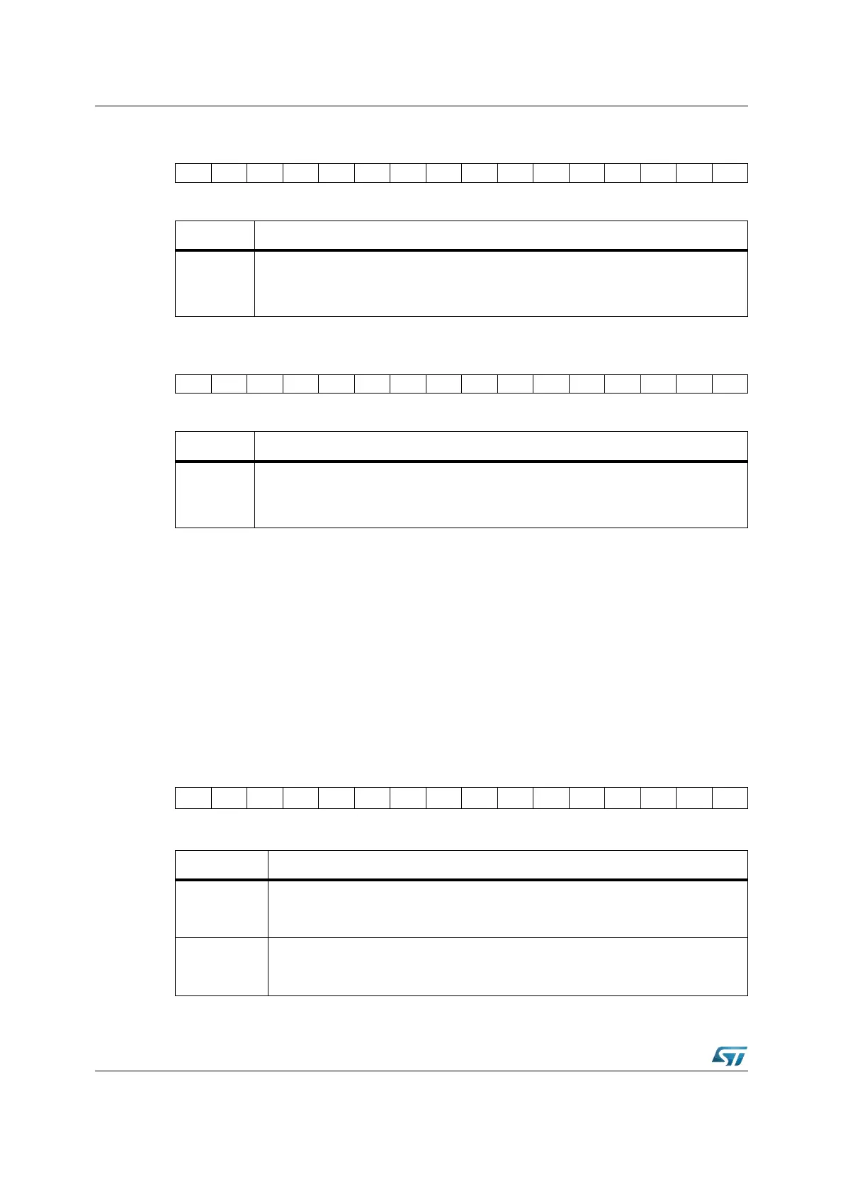
XPWM control register XPWMCON1
Register XPWMCON1 controls the operating modes and the outputs of the four XPWM
channels. The basic operating mode for each channel (standard = edge aligned, or
symmetrical = center aligned PWM mode) is selected by the mode bit PMx. Burst mode
(channels 0 and 1) and single shot mode (channel 2 or 3) are selected by separate control
bit. The output signal of each XPWM channel is individually enabled by bit PENx. If the
output is not enabled the respective pin can be used for general purpose I/O and the XPWM
channel can only be used to generate an interrupt request.
Note: This register is not bit-addressable; the bit-addressability is available via specific ‘set’ and
‘Clear’ write-only registers XPWMCON1SET and XPWMCON1CLR.
XPWMCON1 (EC02h) XBUS Reset Value: 0000h
15 14 13 12 11 10 9 8 7 6 5 4 3 2 1 0
SET.15 SET.14 SET.13 SET.12 SET.11 SET.10 SET.9 SET.8 SET.7 SET.6 SET.5 SET.4 SET.3 SET.2 SET.1 SET.0
WWWWWWWWWWWWWWWW
Bit Function
SET.Y
XPWMCON0 Bit Y Set
Writing a ‘1’ will set the corresponding bit in XPWMCON0 register.
Writing a ‘0’ has no effect.
1514131211109876543210
CLR.15 CLR.14 CLR.13 CLR.12 CLR.11 CLR.10 CLR.9 CLR.8 CLR.7 CLR.6 CLR.5 CLR.4 CLR.3 CLR.2 CLR.1 CLR.0
WWWWWWWWWWWWWWWW
Bit Function
CLR.Y
XPWMCON0 Bit Y Clear
Writing a ‘1’ will clear the corresponding bit in XPWMCON0 register,
Writing a ‘0’ has no effect.
1514131211109876543210
PS3 PS2 - PB01 - - - - PM3 PM2 PM1 PM0 PEN3 PEN2 PEN1 PEN0
RW RW RW RW RW RW RW RW RW RW RW
Bit Function
PENx
XPWM Channel x Output Enable bit
‘0’: Channel x output signal disabled, generate interrupt only
‘1’: Channel x output signal enabled
PMx
XPWM Channel x Mode Control bit
‘0’: Channel x operates in mode 0, that is, edge aligned PWM
‘1’: Channel x operates in mode 1, that is, center aligned PWM