DocID13284 Rev 2 497/564
UM0404 System reset
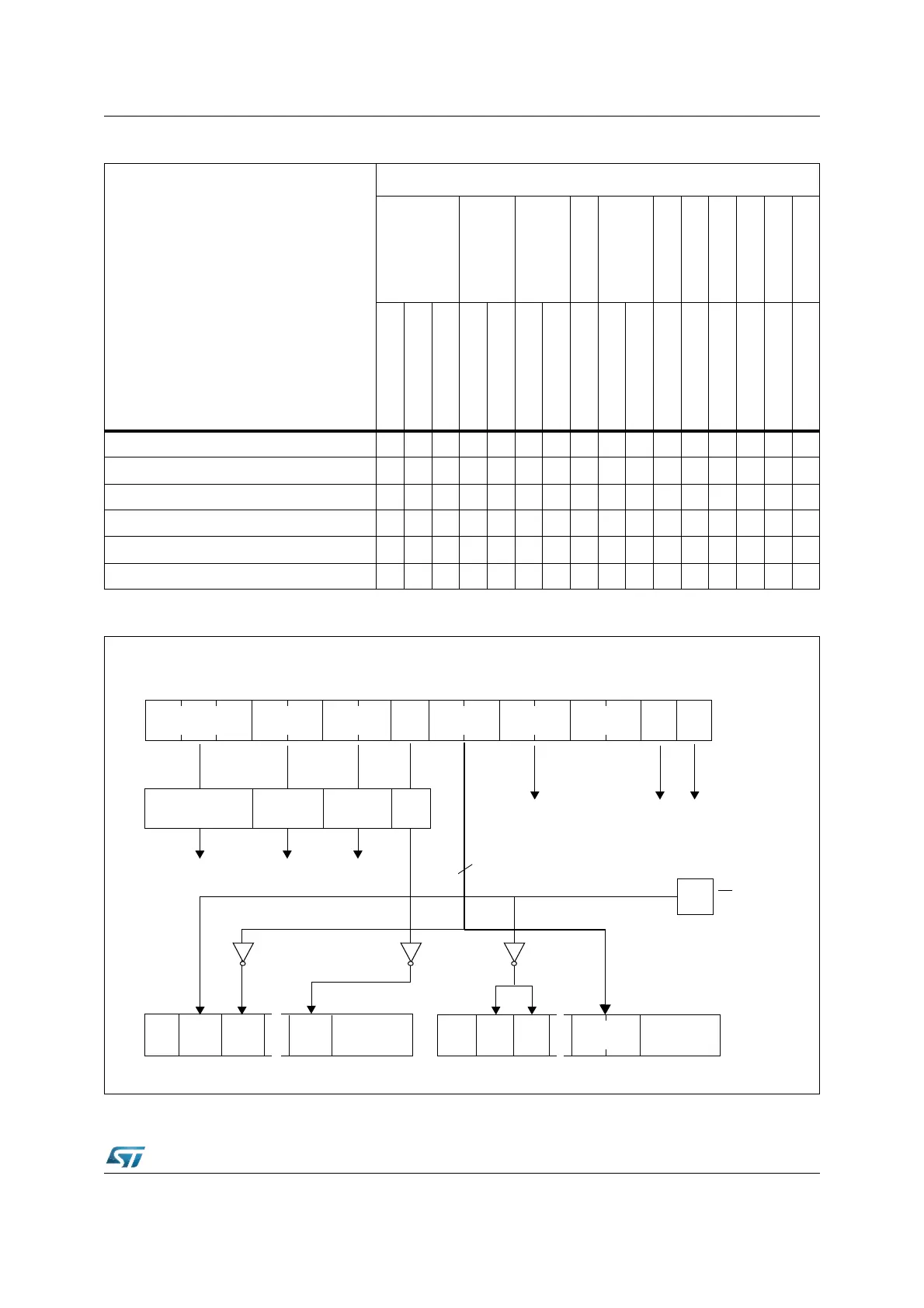
Figure 209. PORT0 bits latched into the different registers after reset
Table 65. PORT0 latched configuration for the different reset events
X : Pin is sampled
- : Pin is not sampled
PORT0
Clock Options
Segm. Addr. Lines
Chip Selects
WR config.
Bus Type
Reserved
BSL
Reserved
Reserved
Adapt Mode
Emu Mode
Sample event
P0H.7
P0H.6
P0H.5
P0H.4
P0H.3
P0H.2
P0H.1
P0H.0
P0L.7
P0L.6
P0L.5
P0L.4
P0L.3
P0L.2
P0L.1
P0L.0
Software Reset - - - XXXXXXX - - ----
Watchdog Reset - - - XXXXXXX - - ----
Synchronous Short Hardware Reset - - - XXXXXXXXXXXXX
Synchronous Long Hardware Reset XXXXXXXXXXXXXXXX
Asynchronous Hardware Reset XXXXXXXXXXXXXXXX
Asynchronous Power-On Reset XXXXXXXXXXXXXXXX
L.5 L.4 L.3 L.2 L.1 L.0H. H. H. H. L.7 L.6H. H. H. H.
RP0H
Clock Port4
Logic
Port6
Logic
SYSCON BUSCON0
Internal Control Logic
7
6
2
P0L.7
P0L.7
79
BYTDIS
WRCFG
PORT0
Bootstrap Loader
Generator
10
9
EA / VSTBY
ROMEN
10