The general purpose timer units UM0404
240/564 DocID13284 Rev 2
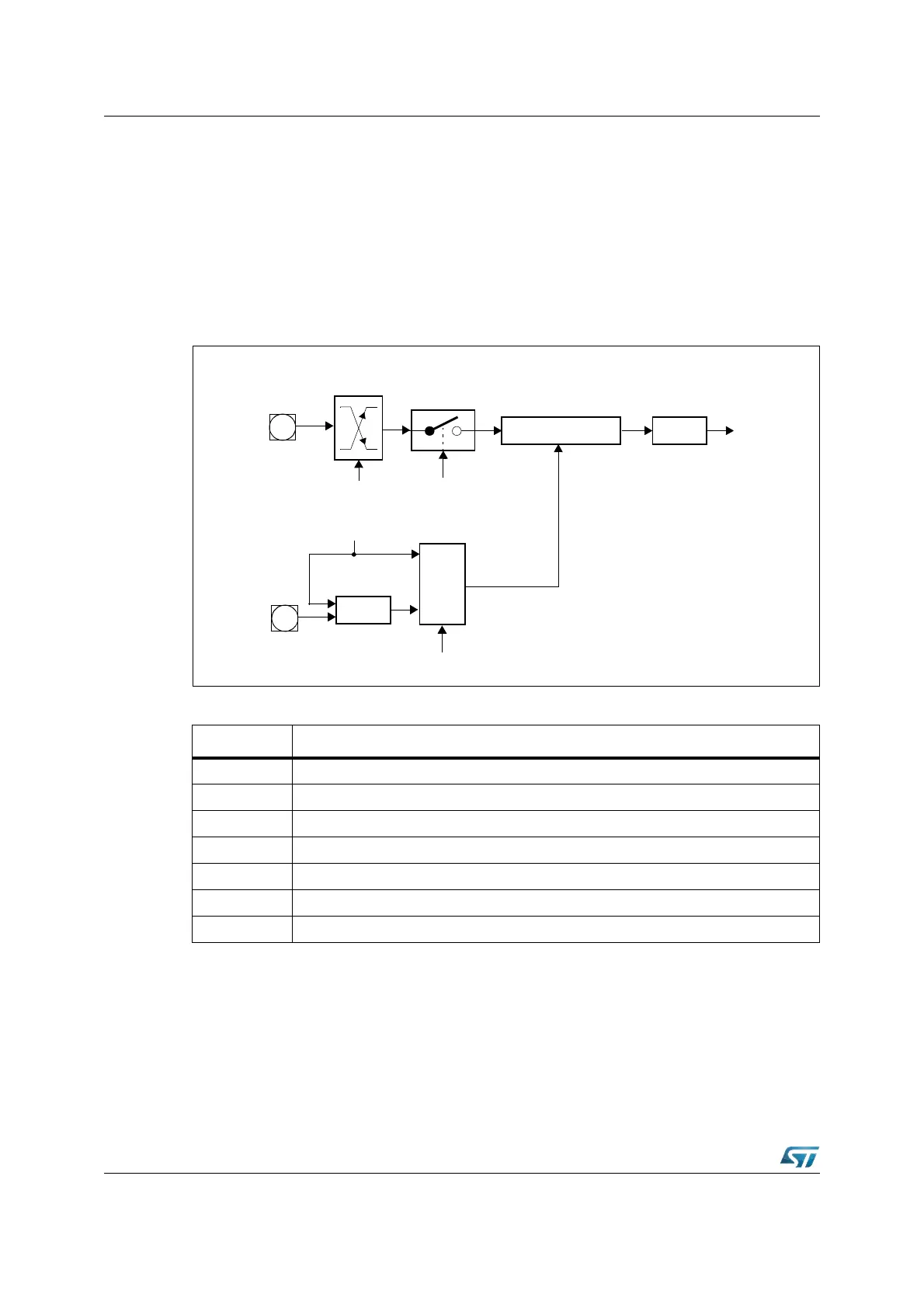
(see Figure 94). Bit-field T5I in control register T5CON selects the triggering transition (see
Table 41).
Note: Only state transitions of T6OTL which are caused by the overflows/underflows of T6 will
trigger the counter function of T5. Modifications of T6OTL via software will NOT trigger the
counter function of T5.
The maximum input frequency allowed in counter mode is f
CPU
/ 4. To ensure that a
transition of the count input signal which is applied to T5IN is correctly recognized, its level
should be held high or low for at least four CPU clock cycles before it changes.
Figure 94. Block diagram of auxiliary timer T5 in counter mode
Timer concatenation
Using the toggle bit T6OTL as a clock source for the auxiliary timer in counter mode
concatenates the core timer T6 with the auxiliary timer. Depending on which transition of
Table 41. GPT2 auxiliary timer (counter mode) input edge selection
T5I Triggering Edge for Counter Increment / Decrement
X 0 0 None. Counter T5 is disabled
0 0 1 Positive transition (rising edge) on T5IN
0 1 0 Negative transition (falling edge) on T5IN
0 1 1 Any transition (rising or falling edge) on T5IN
1 0 1 Positive transition (rising edge) of output toggle latch T6OTL
1 1 0 Negative transition (falling edge) of output toggle latch T6OTL
1 1 1 Any transition (rising or falling edge) of output toggle latch T6OTL
T5R
MUX
T5UDE
Auxiliary Timer T5
T5IR
Interrupt
Request
Up/Down
XOR
1
0
T5UD
T5EUD
T5l
Edge
Select
T5IN
P5.13
P5.11