DocID13284 Rev 2 183/564
UM0404 The external bus interface
8.2 External bus modes
When the external bus interface is enabled (bit BUSACTx = ‘1’ of BUSCONx register) and
configured (bit-field BTYP), the ST10F276 uses a subset of its port lines together with some
control lines to build the external bus.
The bus configuration (BTYP) for the address windows (BUSCON4...BUSCON1) is selected
by software, usually during the initialization of the system.
The bus configuration (BTYP) for the default address range (BUSCON0) is selected via
PORT0 during reset, provided that pin EA
is low during reset. Otherwise BUSCON0 may be
programmed via software just like the other BUSCON registers.
The 16 Mbyte address space of the ST10F276 is divided into 256 segments of 64 Kbytes
each. The 16-bit intra-segment address is output on PORT0 for multiplexed bus modes or
on PORT1 for de-multiplexed bus modes.
When segmentation is disabled, only one 64 Kbyte segment can be used and accessed.
Otherwise, additional address lines may be output on Port4, and/or several chip select lines
may be used to select different memory banks or peripherals. These functions are selected
during reset via bit-fields SALSEL and CSSEL of register RP0H, respectively.
Note: Bit SGTDIS of register SYSCON defines, if the CSP register is saved during interrupt entry
(segmentation active) or not (segmentation disabled).
8.2.1 Multiplexed bus modes
In the multiplexed bus modes the 16-bit intra-segment address and data use PORT0. The
address is time-multiplexed with the data and has to be latched externally.
The width of the required latch depends on the selected data bus width, an 8-bit data bus
requires a byte latch (the address bit A15...A8 on P0H do not change, while P0L multiplexes
address and data), a 16-bit data bus requires a word latch (the least significant address line
A0 is not relevant for word accesses).
The upper address lines (An...A16) are permanently output on Port4 (if segmentation is
enabled) and do not require latches.
The EBC initiates an external access by generating the Address Latch Enable signal (ALE)
and then placing an address on the bus. The falling edge of ALE triggers an external latch to
capture the address.
After a period of time during which the address must have been latched externally, the
address is removed from the bus. The EBC now activates the respective command signal
(RD
, WR, WRL, WRH). Data is driven onto the bus either by the EBC (for write cycles) or by
the external memory/peripheral (for read cycles). After a period of time, which is determined
by the access time of the memory/peripheral, data become valid.
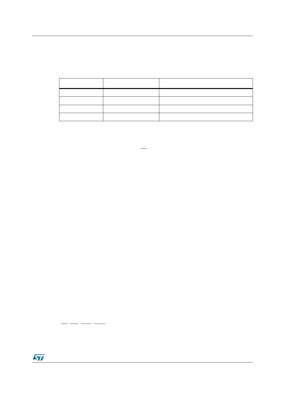
BTYP encoding External data bus width External address bus mode
0 0 8-bit Data De-multiplexed Addresses
0 1 8-bit Data Multiplexed Addresses
1 0 16-bit Data De-multiplexed Addresses
1 1 16-bit Data Multiplexed Addresses