The general purpose timer units UM0404
228/564 DocID13284 Rev 2
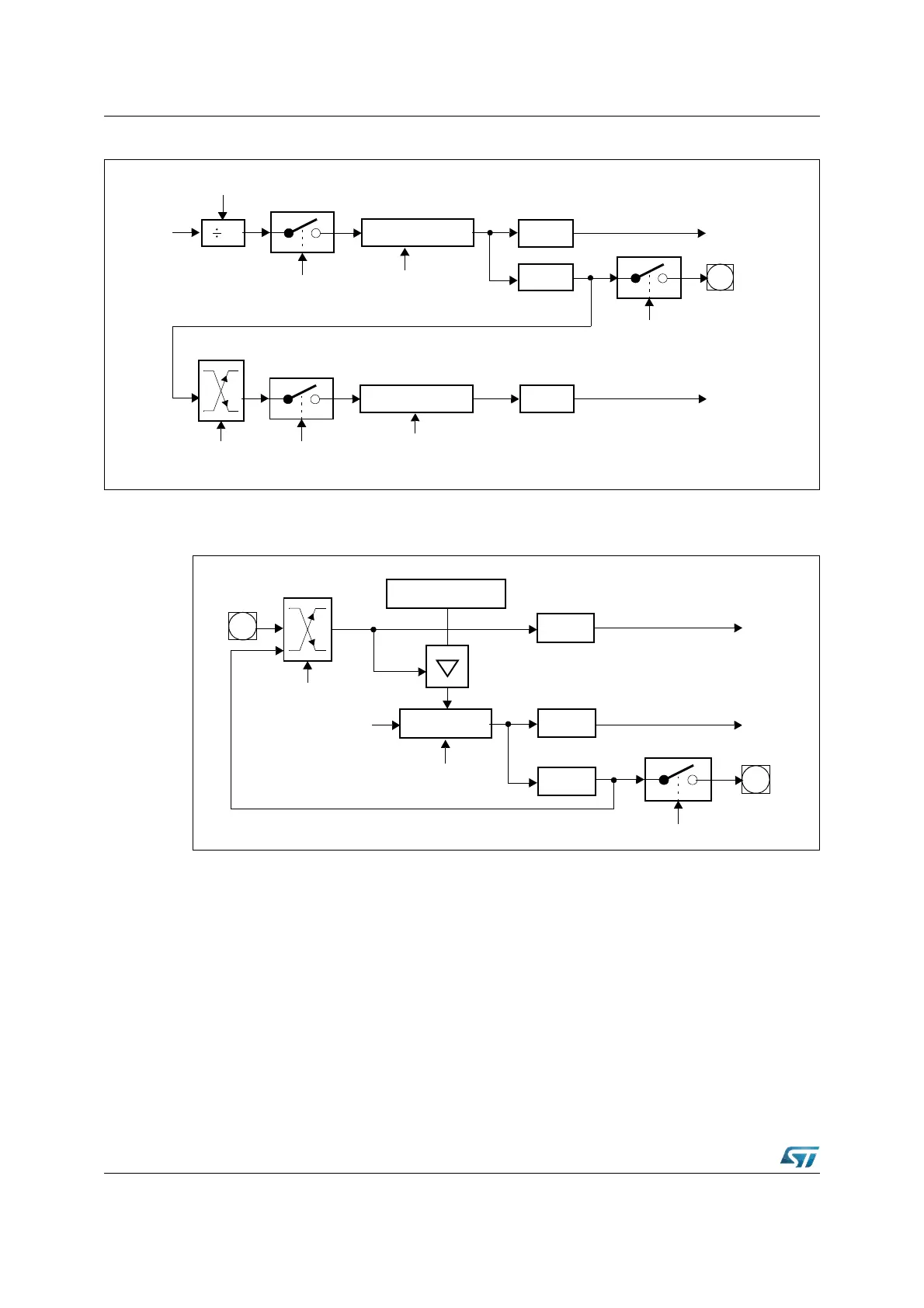
Figure 85. Concatenation of core timer T3 and an auxiliary timer
Note: 1. Line only affected by over/underflows of T3, but NOT by software modifications of T3OTL.
Figure 86. GPT1 auxiliary timer in reload mode
Note: Line only affected by over/underflows of T3, but NOT by software modifications of T3OTL.
Upon a trigger signal T3 is loaded with the contents of the respective timer register (T2 or
T4) and the interrupt request flag (T2IR or T4IR) is set.
Note: When a T3OTL transition is selected for the trigger signal, also the interrupt request flag
T3IR will be set upon a trigger, indicating T3’s overflow or underflow.
Modifications of T3OTL via software will NOT trigger the counter function of T2/T4.
Txl
TxR
Auxiliary Timer Tx
TxIR
Interrupt
Request
T3OTL
Edge
Select
x = 2,4
T3OE
T3IR
Interrupt
1
Core Timer T3
T3R
Up/Down
X
T3l
CPU
Clock
Request
T3OUT
P3.3
Txl
Reload Register Tx
TxIR
Interrupt
Request
Source/Edge
Select
x = 2, 4
Core Timer T3
Up/Down
Input
Clock
T3IR
Interrupt
Request
T3OTL
T3OE
T3OUT
P3.3
TxIN
P3.7
1)
P3.5