DocID13284 Rev 2 293/564
UM0404 XBUS high-speed synchronous serial interface
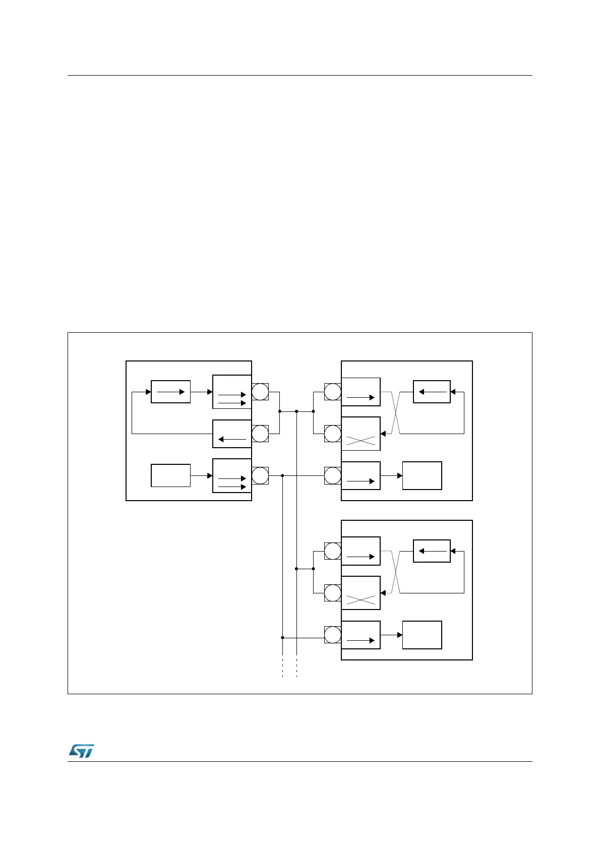
13.2 Half duplex operation
In a half duplex configuration only one data line is necessary for both receiving and
transmitting of data. The data exchange line is connected to both pins MTSR1 and MRST1
of each device, the clock line is connected to the SCLK1 pin.
The master device controls the data transfer by generating the shift clock, while the slave
devices receive it. Due to the fact that all transmit and receive pins are connected to the one
data exchange line, serial data may be moved between arbitrary stations.
Similar to full duplex mode there are two ways to avoid collisions on the data exchange
line:
• Only the transmitting device may enable its transmit pin driver
• The non-transmitting devices use open drain output and only send ones.
Since the data inputs and outputs are connected together, a transmitting device will clock in
its own data at the input pin (MRST1 for a master device, MTSR1 for a slave). By these
means any corruptions on the common data exchange line are detected, where the
received data is not equal to the transmitted data.
Figure 121. XSSC half duplex configuration
Shift Register
MTSR1
CLK
MRST1
Clock
Master
Device #1
Clock
MTSR1
CLK
Clock
Shift Register
Device #2 Slave
MTSR1
MRST1
CLK
Clock
Shift Register
Device #3 Slave
MRST1
Common
Transmit/
Receive
Line