XBUS pulse width modulation module UM0404
368/564 DocID13284 Rev 2
also the common interrupt request line is asserted (XP2IR/XP3IR in registers
XP2IC/XP3IC), provided that they are enabled via the common interrupt enable bits
(XP2IE/XP3IE) and the dedicated enable bits inside XIRSEL2/XIRSEL3 registers.
Note: The channel interrupt request flags (PIRx in register XPWMCON0) are not automatically
cleared by hardware upon entry into the interrupt service routine, so they must be cleared
via software. The module interrupt request flags XP2IR/XP3IR are also not cleared by
hardware upon entry into the service routine, regardless of how many channel interrupts
were active. However, it will be set again if during execution of the service routine a new
channel interrupt request is generated.
18.4 XPWM output signals
The output signals of the four XPWM channels (XPOUT3...XPOUT0) are alternate output
functions on Port8 (P8.3...P8.0). The XPWM signals are XORed with the outputs of the
register XPOLAR before being driven to the port pins. This allows driving the XPWM signal
directly to the port pin (XPOLAR.x = ‘0’) or drive the inverted XPWM signal
(XPOLAR.x = ‘1’). At Port8 level, when output direction is enabled, and bit XPWMEN of
XPERCON is set, it is again possible to control the polarity like it is done for the standard
PWM (on Port7), simply setting or clearing the output data register P8.x (x = 0...3);
maintaining cleared the data register, the polarity is not inverted, while it is inverted setting
the register. Note that if bit XP8.y (XPWMPORT register) is set, the polarity is inverted as
well: so, if both XPOLAR.y and XP8.y are set, no inversion is achieved. For Port8 block
diagram, refer also to Section 6.10: Port8 on page 172.
The PWM signals are XORed with the respective port latch outputs before being driven to
the port pins.
This allows driving the PWM signal directly to the port pin (P8.x = ‘0’) or drive the inverted
PWM signal (P8.x = ‘1’) (see Figure 150 on page 356).
Note: Using the open-drain mode on Port8 allows the combination of two or more XPWM outputs
through a AND-Wired configuration, using an external pull-up device. This provides sort of a
burst mode for any XPWM channel.
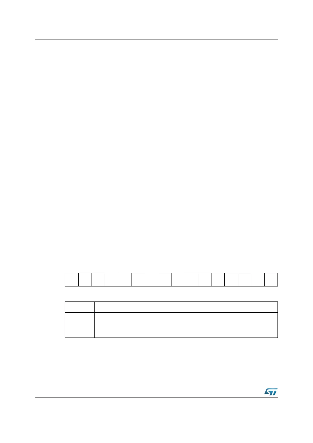
XPOLAR (EC04h) XBUS Reset Value: 0000h
Software control of the XPWM outputs
In an application the XPWM output signals are generally controlled by the XPWM module.
However, it may be necessary to influence the level of the XPWM output pins via software
1514131211109876543210
------------
XPO
LAR.3
XPO
LAR.2
XPO
LAR.1
XPO
LAR.0
RW RW RW RW
Bit Function
XPOLAR.Y
XPWM Channel Y Polarity Bit
‘0’: Polarity of Channel Y is normal
‘1’: Polarity of Channel Y is inverted