DocID13284 Rev 2 453/564
UM0404 CAN modules
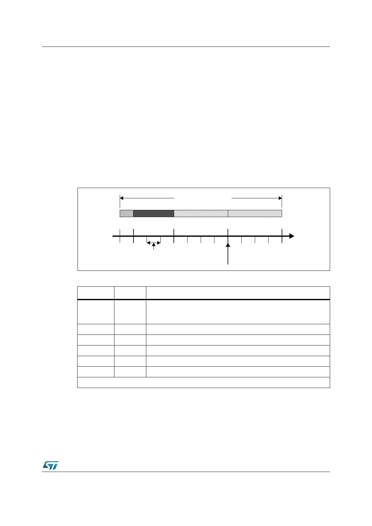
According to the CAN specification, the bit time is divided into four segments (see
Figure 182): the Synchronization Segment, the Propagation Time Segment, the Phase
Buffer Segment 1 and the Phase Buffer Segment 2. Each segment consists of a specific,
programmable number of time quanta (see Table 62). The length of the time quantum (t
q
),
which is the basic time unit of the bit time, is defined by the CAN controller’s system clock
f
sys
and the Baud Rate Prescaler (BRP): t
q
= BRP / f
sys
. The C-CAN’s system clock f
sys
is
the frequency of its CAN module clock input (see f
CPU
).
The Synchronization Segment Sync_Seg is that part of the bit time where edges of the CAN
bus level are expected to occur; the distance between an edge that occurs outside of
Sync_Seg and the Sync_Seg is called the phase error of that edge. The Propagation Time
Segment Prop_Seg is intended to compensate for the physical delay times within the CAN
network. The Phase Buffer Segments Phase_Seg1 and Phase_Seg2 surround the Sample
Point. The (Re-)Synchronization Jump Width (SJW) defines how far a resynchronization
may move the Sample Point inside the limits defined by the Phase Buffer Segments to
compensate for edge phase errors.
Figure 182. Bit timing
A given bitrate may be met by different bit time configurations, but for the proper function of
the CAN network the physical delay times and the oscillator’s tolerance range have to be
considered.
Table 62. Parameters of the CAN bit time
Parameter Range Remark
BRP
BRP +
BRPE
[1 .. 32]
[1 .. 512]
defines the length of the time quantum
t
q
Sync_Seg 1
t
q
fixed length, synchronization of bus input to system clock
Prop_Seg [1 .. 8]
t
q
compensates for the physical delay times
Phase_Seg1 [1 .. 8]
t
q
may be lengthened temporarily by synchronization
Phase_Seg2 [1 .. 8]
t
q
may be shortened temporarily by synchronization
SJW [1 .. 4]
t
q
may not be longer than either Phase Buffer Segments
This table describes the minimum programmable ranges required by the CAN protocol
1 Time Quantum
(t
q
)
Sync_ Prop_Seg Phase_Seg1 Phase_Seg2
Sample Point
Nominal CAN Bit Time
Seg