DocID13284 Rev 2 335/564
UM0404 The capture / compare units
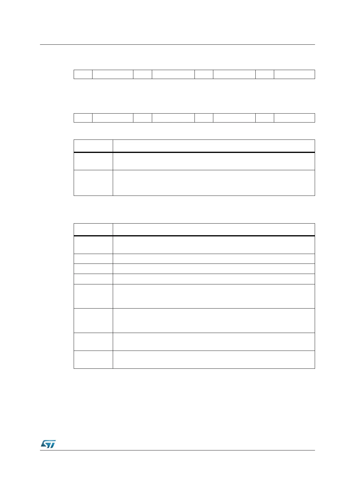
CCM6 (FF26h / 93h) SFR Reset Value: 0000h
CCM7 (FF28h / 94h) SFR Reset Value: 0000h
16.3.1 Selection of capture modes and compare modes
The detailed discussion of the capture and compare modes is valid for all the capture /
compare channels, so registers, bits and pins are only referenced by the place holder ‘x’.
Note: Capture / compare channels 24...27 generate an interrupt request but do not provide an
output signal. The resulting exceptions are indicated in the following subsections.
A capture or compare event on channel 31 may be used to trigger a channel injection on the
ST10F276’s A / D converter if enabled.
15 14 13 12 11 10 9 8 7 6 5 4 3 2 1 0
ACC27 CCMOD27 ACC26 CCMOD26 ACC25 CCMOD25 ACC24 CCMOD24
RW RW RW RW RW RW RW RW
15 14 13 12 11 10 9 8 7 6 5 4 3 2 1 0
ACC31 CCMOD31 ACC30 CCMOD30 ACC29 CCMOD29 ACC28 CCMOD28
RW RW RW RW RW RW RW RW
Bit Function
CCMODx
Mode Selection for Capture / Compare Register CCx
The available capture / compare modes are listed in the table below.
ACCx
Allocation bit for Capture / Compare Register CCx
‘0’: CCx allocated to Timer T0 (CAPCOM1) / Timer T7 (CAPCOM2)
‘1’: CCx allocated to Timer T1 (CAPCOM1) / Timer T8 (CAPCOM2)
CCMODx Selected Operating Mode
0 0 0
Disable Capture and Compare Modes
The respective CAPCOM register may be used for general variable storage.
0 0 1 Capture on Positive Transition (Rising Edge) at Pin CCxIO
0 1 0 Capture on Negative Transition (Falling Edge) at Pin CCxIO
0 1 1 Capture on Positive and Negative Transition (Both Edges) at Pin CCxIO
1 0 0
Compare Mode 0: Interrupt Only
Several interrupts per timer period. Enables double-register compare mode for
registers CC8...CC15 and CC24...CC31.
1 0 1
Compare Mode 1: Toggle Output Pin on each Match
Several compare events per timer period. This mode is required for double-register
compare mode for registers CC0...CC7 and CC16...CC23.
1 1 0
Compare Mode 2: Interrupt Only
Only one interrupt per timer period.
1 1 1
Compare Mode 3: Set Output Pin on each Match
Reset output pin on each timer overflow. Only one interrupt per timer period.