DocID13284 Rev 2 99/564
UM0404 Interrupt and trap functions
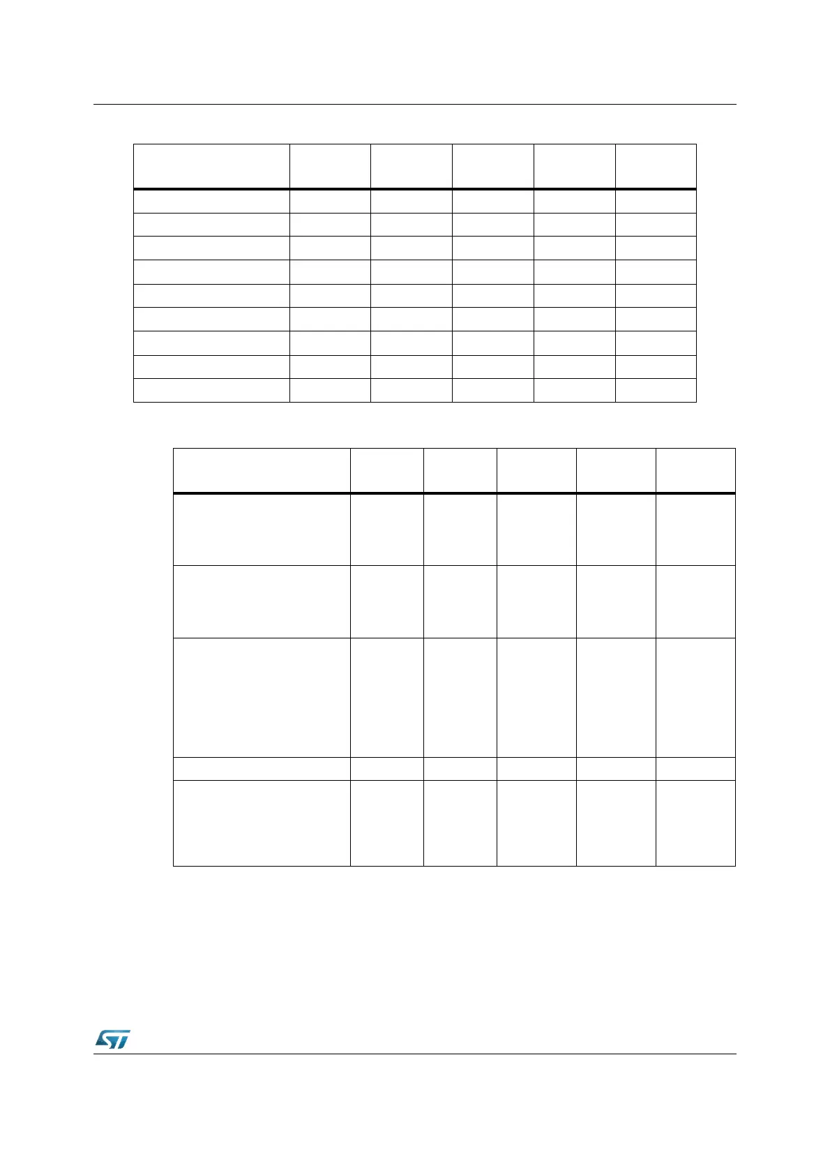
The Ta ble 16 lists the vector locations for hardware traps and the corresponding status flags
in register TFR.
It also lists the priorities of trap service for cases, where more than one trap condition might
be detected within the same instruction.
After any reset (hardware reset, software reset instruction SRST, or reset by watchdog timer
overflow) program execution starts at the reset vector at location 00’0000h.
ASC0 Error S0EIR S0EIE S0EINT 00’00B0h 2Ch
SSC Transmit SSCTIR SSCTIE SSCTINT 00’00B4h 2Dh
SSC Receive SSCRIR SSCRIE SSCRINT 00’00B8h 2Eh
SSC Error SSCEIR SSCEIE SSCEINT 00’00BCh 2Fh
PWM Channel 0...3 PWMIR PWMIE PWMINT 00’00FCh 3Fh
See Section 5.7 XP0IR XP0IE XP0INT 00’0100h 40h
See Section 5.7 XP1IR XP1IE XP1INT 00’0104h 41h
See Section 5.7 XP2IR XP2IE XP2INT 00’0108h 42h
See Section 5.7 XP3IR XP3IE XP3INT 00’010Ch 43h
Table 15. Interrupt and PEC service request sources (continued)
Source of interrupt or
PEC service request
Request
flag
Enable
flag
Interrupt
vector
Vector
location
Trap
number
Table 16. Vector locations and status for hardware traps
Exception condition
Trap
flag
Trap
vector
Vector
location
Trap
number
Trap
priority
RESET Functions:
Hardware RESET
Software RESET
Watchdog Timer Overflow
RESET
RESET
RESET
00’0000h
00’0000h
00’0000h
00h
00h
00h
MAXIMAL
III
III
III
Class A Hardware Traps:
Non-Maskable Interrupt
Stack Overflow
Stack Underflow
NMI
STKOF
STKUF
NMITRAP
STOTRAP
STUTRAP
00’0008h
00’0010h
00’0018h
02h
04h
06h
II
II
II
Class B Hardware Traps:
Undefined Opcode
MAC Interruption
Protected Instruction Fault
Illegal Word Operand Access
Illegal Instruction Access
Illegal External Bus Access
UNDOPC
MACTRP
PRTFLT
ILLOPA
ILLINA
ILLBUS
BTRAP
BTRAP
BTRAP
BTRAP
BTRAP
BTRAP
00’0028h
00’0028h
00’0028h
00’0028h
00’0028h
00’0028h
0Ah
0Ah
0Ah
0Ah
0Ah
0Ah
I
I
I
I
I
I minimal
Reserved [2Ch –3Ch] [0Bh – 0Fh]
Software Traps
TRAP Instruction
Any
[00’0000h–
00’01FCh]
in steps of
4h
Any
[00h – 7Fh]
Current
CPU
Priority