DocID13284 Rev 2 475/564
UM0404 System reset
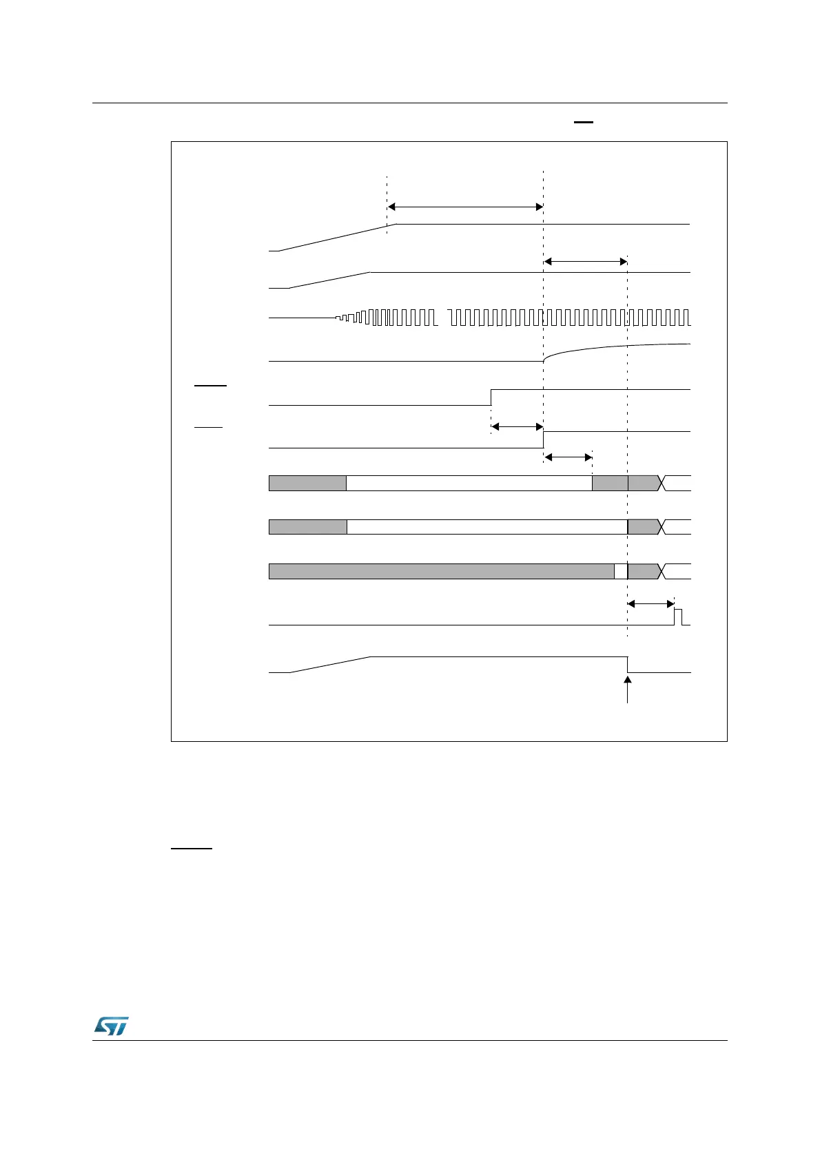
Figure 193. Asynchronous power-on RESET (EA = 0)
Hardware reset
The asynchronous reset must be used to recover from catastrophic situations of the
application. It may be triggered by the hardware of the application. Internal hardware logic
and application circuitry are described in Section 23: System reset on page 472 and in
Figure 205 on page 491, Figure 206 on page 492 and Figure 3 on page 30. It occurs when
RSTIN
is low and RPD is detected (or becomes) low as well.
RSTIN
P0[15:13]
P0[12:2]
not t.
transparent
not t.
P0[1:0] not t.
not transparent
V
18
XTAL1
...
3..8 TCL
1)
RST
Latching point of Port0 for
system start-up configuration
V
DD
≥ 1 ms (for on-chip VREG stabilization)
RPD
ALE
≥ 1.2 ms (for resonator oscillation + PLL stabilization)
≥ 10.2 ms (for crystal oscillation + PLL stabilization)
Note 1. 3 to 8 TCL depending on clock source selection.
RSTF
≤ 500 ns
(After Filter)
≥ 50 ns
8 TCL
transparent
3..4 TCL