DocID13284 Rev 2 461/564
UM0404 CAN modules
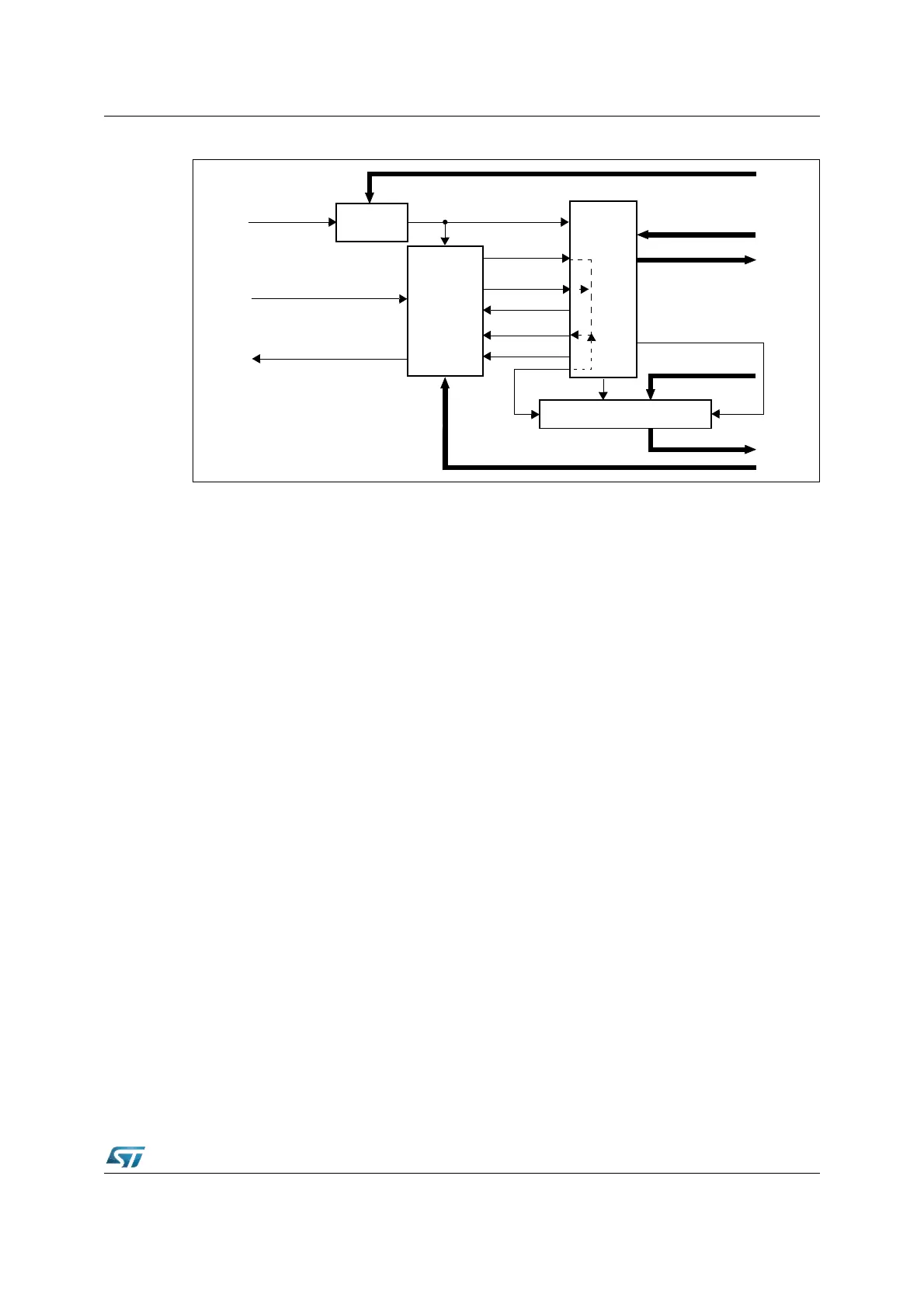
Figure 186. Structure of the CAN Core’s CAN protocol controller
The data in the bit timing registers are the configuration input of the CAN protocol controller.
The Baud Rate Prescaler (configured by BRP) defines the length of the time quantum, the
basic time unit of the bit time; the Bit Timing Logic (configured by TSeg1, TSeg2, and SJW)
defines the number of time quanta in the bit time.
The processing of the bit time, the calculation of the position of the Sample Point, and
occasional synchronizations are controlled by the BTL state machine, which is evaluated
once each time quantum. The rest of the CAN protocol controller, the Bit Stream Processor
(BSP) state machine is evaluated once each bit time, at the Sample Point.
The Shift Register serializes the messages to be sent and parallelizes received messages.
Its loading and shifting is controlled by the BSP.
The BSP translates messages into frames and vice versa. It generates and discards the
enclosing fixed format bits, inserts and extracts stuff bits, calculates and checks the CRC
code, performs the error management, and decides which type of synchronization is to be
used. It is evaluated at the Sample Point and processes the sampled bus input bit. The time
after the Sample point that is needed to calculate the next bit to be sent (for example, data
bit, CRC bit, stuff bit, error flag, or idle) is called the Information Processing Time (IPT).
The IPT is application specific but may not be longer than 2 t
q
; the C-CAN’s IPT is 0 t
q
. Its
length is the lower limit of the programmed length of Phase_Seg2. In case of a
synchronization, Phase_Seg2 may be shortened to a value less than IPT, which does not
affect bus timing.
Calculation of the bit timing parameters
Usually, the calculation of the bit timing configuration starts with a desired bitrate or bit time.
The resulting bit time (1/ bit rate) must be an integer multiple of the system clock period.
The bit time may consist of 4 to 25 time quanta, the length of the time quantum t
q
is defined
by the Baud Rate Prescaler with t
q
= (Baud Rate Prescaler) / f
sys
. Several combinations
may lead to the desired bit time, allowing iterations of the following steps.
First part of the bit time to be defined is the Prop_Seg. Its length depends on the delay times
measured in the system. A maximum bus length as well as a maximum node delay has to
Sample_Point
Bit_to_send
Sync_Mode
Bus_Off
Scaled_Clock (t
q
)
System Clock
Receive_Data
Transmit_Data
Control
Received_Message
Send_Message
Status
Bit
Timing
Logic
Baudrate
Prescaler
Sampled_Bit
Configuration (TSeg1, TSeg2, SJW)
Configuration (BRP)
Shift-Register
Received_Data_Bit
Next_Data_Bit
Control
Bit Stream Processor
IPT