DocID13284 Rev 2 223/564
UM0404 The general purpose timer units
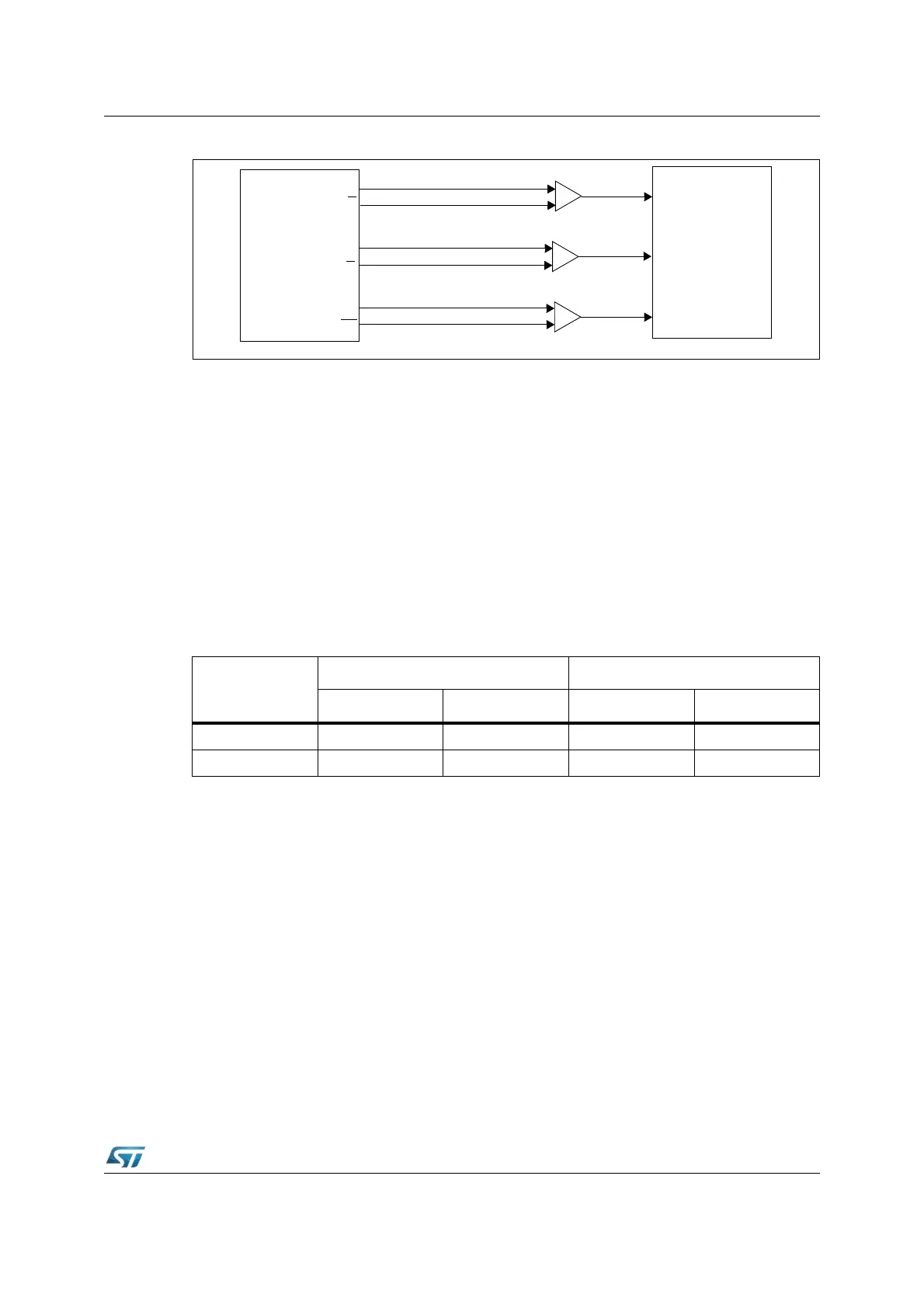
Figure 81. Connection of the encoder to the ST10F276
For incremental interface operation the following conditions must be met
• Bit-field T3M must be ‘110b’
• Both pins T3IN and T3EUD must be configured as input, at the respective direction
control bit with ‘0’.
• Bit T3EUD must be ‘1’ to enable automatic direction control.
The maximum allowed input frequency in incremental interface mode is f
CPU
/ 16. To ensure
correct recognition of the transition of any input signal, its level should be held high or low
for at least eight CPU clock cycles.
In incremental interface mode, the count direction is automatically derived from the
sequence in which the input signals change.
This corresponds to the rotation direction of the connected sensor. The table below
summarizes the possible combinations.
The Figure 82 gives examples of T3’s operation, visualizing count signal generation and
direction control.
It also shows how input jitter is compensated. This might occur if the sensor stays near to
one of the switching points.
Level on
respective other
input
T3IN input T3EUD input
Rising Falling Rising Falling
High Down Up Up Down
Low Up Down Down Up
T3input
T3input
Interrupt
ST10F276x
A
B
T0
A
A
B
B
T0
T0
ENCODER
Signal Conditioning