System programming UM0404
548/564 DocID13284 Rev 2
The contents of the stack pointer are compared to the contents of the underflow register,
whenever the SP is INCREMENTED either by a RET, POP or ADD instruction. An underflow
trap will be entered, when the SP value is greater than the value in the stack underflow
register.
Note: When a value is MOVED into the stack pointer, NO check against the overflow/underflow
registers is performed.
In many cases the user will place a software reset instruction (SRST) into the stack
underflow and overflow trap service routines. This is an easy approach, which does not
require special programming.
However, this approach assumes that the defined internal stack is sufficient for the current
software and that exceeding its upper or lower boundary represents a fatal error.
It is also possible to use the stack underflow and stack overflow traps to cache portions of a
larger external stack. Only the portion of the system stack currently being used is placed into
the internal memory, thus allowing a greater portion of the IRAM to be used for program,
data or register banking. This approach assumes no error but requires a set of control
routines (see below).
Circular (virtual) stack
This basic technique allows pushing until the overflow boundary of the internal stack is
reached. At this point a portion of the stacked data must be saved into external memory to
create space for further stack pushes.
This is called “stack flushing”. When executing a number of return or pop instructions, the
upper boundary (since the stack empties upward to higher memory locations) is reached.
The entries that have been previously saved in external memory must now be restored.
This is called “stack filling”. Because procedure call instructions do not continue to nest
infinitely and call and return instructions alternate, flushing and filling normally occurs very
infrequently. If this is not true for a given program environment, this technique should not be
used because of the overhead of flushing and filling.
The basic mechanism is the transformation of the addresses of a virtual stack area,
controlled via registers SP, STKOV and STKUN, to a defined physical stack area within the
IRAM via hardware. This virtual stack area covers all possible locations that SP can point to,
from 00’F000h through 00’FFFEh. STKOV and STKUN accept the same 4 Kbyte address
range.
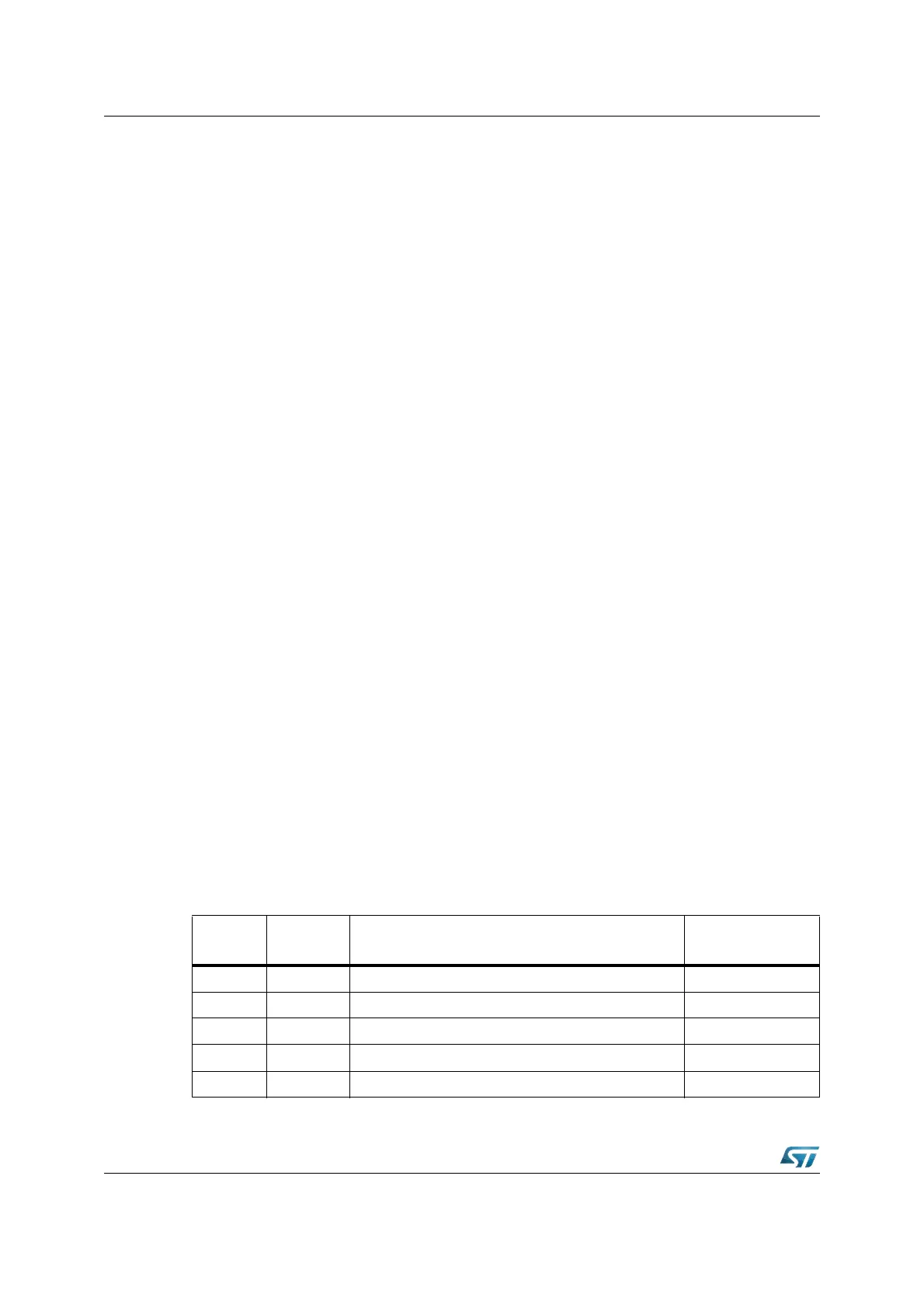
The size of the physical stack area within the IRAM that effectively is used for standard
stack operations is defined via bit-field STKSZ in register SYSCON (see below).
Table 76. Stack size selection
(STKSZ)
Stack size
(words)
IRAM addresses (words)
of physical stack
Significant bit of
stack pointer SP
0 0 0 b 256 00’FBFEh...00’FA00h (Default after Reset) SP.8...SP.0
0 0 1 b 128 00’FBFEh...00’FB00h SP.7...SP.0
0 1 0 b 64 00’FBFEh...00’FB80h SP.6...SP.0
0 1 1 b 32 00’FBFEh...00’FBC0h SP.5...SP.0
1 0 0 b 512 00’FBFEh...00’F800h (not for 1 Kbyte IRAM) SP.9...SP.0