System reset UM0404
496/564 DocID13284 Rev 2
23.9.1 System start-up configuration
Although most programmable features are either selected during the initialization phase or
repeatedly during program execution, there are some features that must be selected earlier
because they are used for the first access of the program execution (for example internal or
external start selected via EA
).
These selections are made during reset by the pins of PORT0 which are read at the end of
the internal reset sequence. During reset, internal pull-up devices are active on the PORT0
lines so their input level is high, if the respective pin is left open, or is low, if the respective
pin is connected to an external pull-down device. With the coding of the selections, as
shown below, in many cases the default option (high level), can be used.
The value on the upper byte of PORT0 (P0H) is latched into register RP0H upon reset, the
value on the lower byte (P0L) directly influences the BUSCON0 register (bus mode) or the
internal control logic of the ST10F276.
Not all PORT0 bits are latched after the end of an internal reset. Depending on the reset
type, different bits are latched.
When RSTIN
goes active, the PORT0 configuration input pins are not transparent for the
first 1024 TCL.
After that time only, the PORT0 pins are transparent and will be latched when internal reset
signal becomes inactive (see falling edge of internal signal RST in Figure 192 on page 474
to Figure 199 on page 483). To avoid unexpected behavior, the level of the PORT0
configuration input pins should not change while PORT0 is transparent.
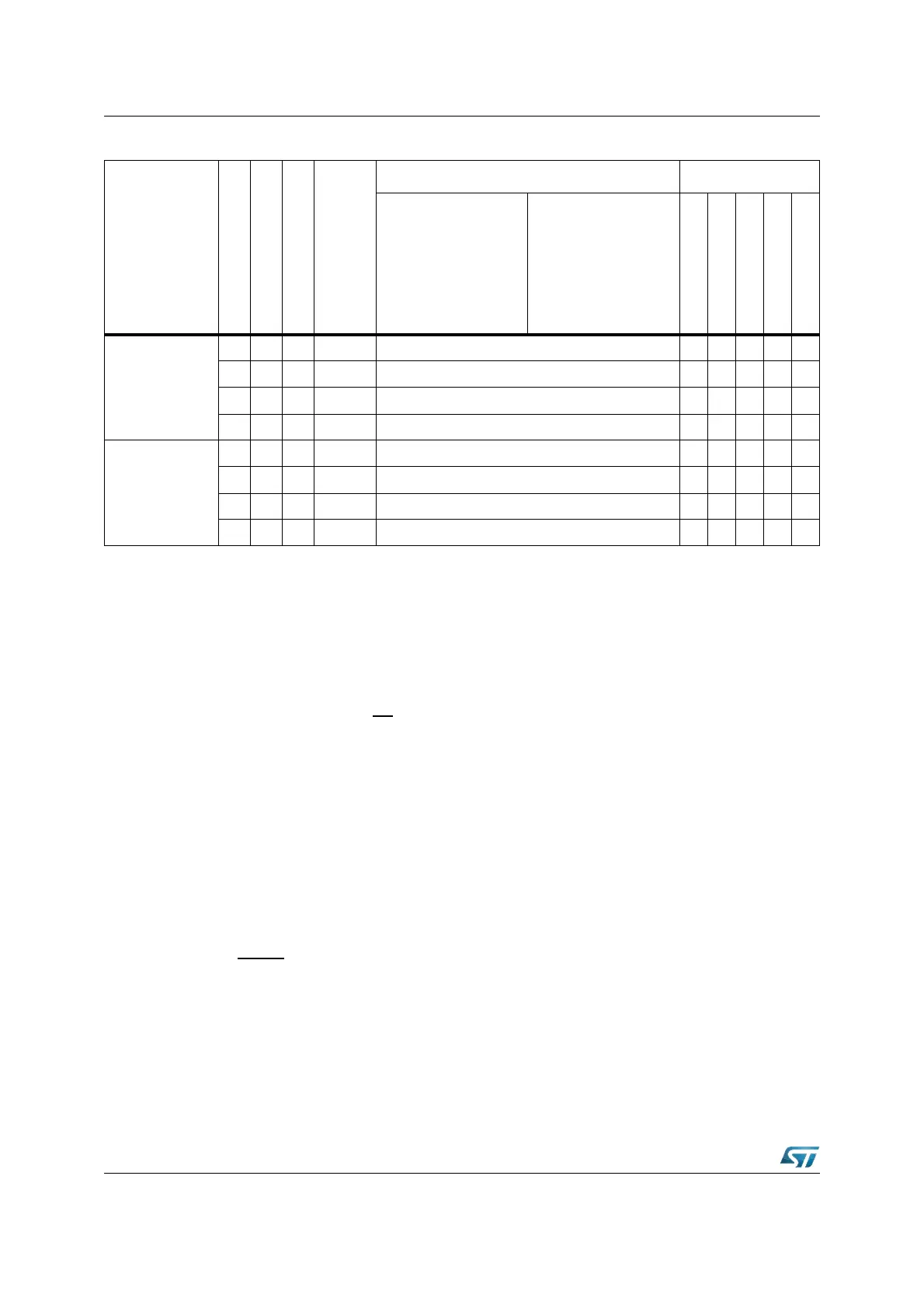
Software reset
(2)
x 0 N Synch. Not activated 0 0 0 1 0
x 0 N Synch. Not activated 0 0 0 1 0
0 1 Y Synch. Not activated 0 0 0 1 0
1 1 Y Synch. Activated by internal logic for 1024 TCL 0 0 0 1 0
Watchdog reset
(2)
x 0 N Synch. Not activated 0 0 0 1 1
x 0 N Synch. Not activated 0 0 0 1 1
0 1 Y Synch. Not activated 0 0 0 1 1
1 1 Y Synch. Activated by internal logic for 1024 TCL 0 0 0 1 1
1. It can degenerate into a Long Hardware Reset and consequently differently flagged (see Section 24.3 for details).
2. When Bidirectional is active (and with RPD
= 0), it can be followed by a Short Hardware Reset and consequently
differently flagged (see Section 23.6: Bidirectional reset for details).
Table 64. Reset events summary (continued)
Event
RPD
EA
Bidir
Synch.
asynch.
RSTIN WDTCON flags
min max
PONR
LHWR
SHWR
SWR
WDTR