DocID13284 Rev 2 477/564
UM0404 System reset
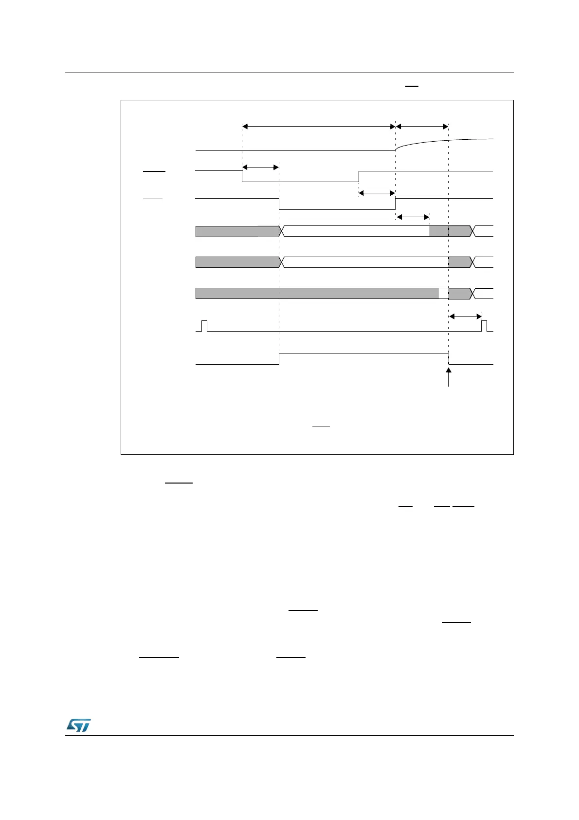
Figure 195. Asynchronous hardware RESET (EA = 0)
Exit from asynchronous reset state
When the
RSTIN
pin is pulled high, the device restarts: as already mentioned, if internal
Flash is used, the restarting occurs after the embedded Flash initialization routine is
completed. The system configuration is latched from Port0: ALE, RD
and WR/WRL pins are
driven to their inactive level. The ST10F276 starts program execution from memory location
00'0000h in code segment 0. This starting location will typically point to the general
initialization routine. Timing of asynchronous Hardware Reset sequence are summarized in
Figure 194 and Figure 195.
23.3 Synchronous reset (warm reset)
A synchronous reset is triggered when RSTIN pin is pulled low while RPD pin is at high
level. In order to properly activate the internal reset logic of the device, the RSTIN
pin must
be held low, at least, during 4 TCL (2 periods of CPU clock): refer also to Section 23.1: Input
filter for details on minimum reset pulse duration. The I/O pins are set to high impedance
and RSTOUT
pin is driven low. After RSTIN level is detected, a short duration of a maximum
of 12 TCL (6 periods of CPU clock) elapses, during which pending internal hold states are
cancelled and the current internal access cycle if any is completed. External bus cycle is
RSTF
P0[15:13]
P0[12:2]
transparent
not t.
transparent
not t.
P0[1:0] not t.
not transparent
3..8 TCL
2)
RST
Latching point of Port0 for
system start-up configuration
RPD
ALE
1)
Note 2. 3 to 8 TCL depending on clock source selection.
not transparent
not transparent
Note 1. Longer than Port0 settling time + PLL synchronization (if needed, that is P0(15:13) changed)
Longer than 500ns to take into account of Input Filter on RSTIN
pin
(After Filter)
RSTIN
≤ 500 ns
≥ 50 ns
≤ 500 ns
≥ 50 ns
8 TCL
3..4 TCL