DocID13284 Rev 2 299/564
UM0404 Watchdog timer
A watchdog reset will also complete a running external bus cycle before starting the internal
reset sequence if this bus cycle does not use READY
or samples READY active (low) after
the programmed wait-states. Otherwise the external bus cycle will be aborted.
After a hardware reset that activates the Bootstrap Loader the watchdog timer will be
disabled.
To prevent the watchdog timer from overflowing, it must be serviced periodically by the user
software. The watchdog timer is serviced with the instruction SRVWDT, which is a protected
32-bit instruction. Servicing the watchdog timer clears the low byte and reloads the high byte
of the watchdog time register WDT with the preset value in bit-field WDTREL, which is the
high byte of register WDTCON. Servicing the watchdog timer will also reset bit WDTR.
After being serviced the watchdog timer continues counting up from the value [(WDTREL) x
2
8
]. Instruction SRVWDT has been encoded in such a way that the chance of unintentionally
servicing the watchdog timer (for example, by fetching and executing a bit pattern from a
wrong location) is minimized. When instruction SRVWDT does not match the format for
protected instructions, the Protection Fault Trap will be entered, rather than the instruction
be executed.
The PONR flag of WDTCON register is set if the output voltage of the internal 1.8V supply
falls below the threshold (typically 1.65V) of the Power-On detection circuit. This circuit is
efficient to detect major failures of the external 5V supply but if the internal 1.8V supply does
not drop under 1.65 volts, the PONR flag is not set. This could be the case on fast switch-off
/ switch-on of the 5V supply. The time needed for such a sequence to activate the PONR
flag depends on the value of the capacitors connected to the supply and on the exact value
of the internal threshold of the detection circuit.
Note: 1 PONR bit may not be set for short supply failure.
2 For Power-On reset and reset after supply partial failure, asynchronous reset must be used.
In
Table 44 a summary of the different reset events and consequent WDTCON flag setting is
reported. Refer also to Section 23: System reset on page 472 for details.
The Watchdog Timer is 16-bit, clocked with the system clock divided by 2 or 128. The high
byte of the watchdog timer register can be set to a pre-specified reload value (stored in
WDTREL).
Each time it is serviced by the application software, the high byte of the watchdog timer is
reloaded. For security, rewrite WDTCON each time before the watchdog timer is serviced.
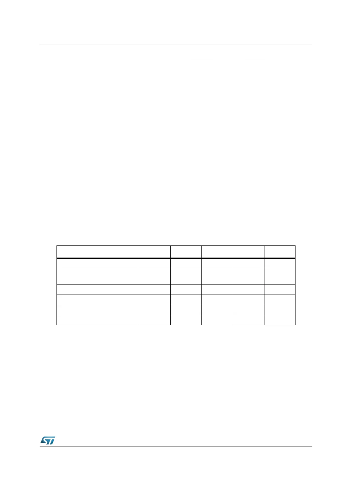
Table 42. WDTCON bits value on different resets
Reset source PONR LHWR SHWR SWR WDTR
Power-On Reset X X X X
Power-On after partial supply
failure
Note 1 X X X
Long Hardware Reset X X X
Short Hardware Reset X X
Software Reset X
Watchdog Reset X X