DocID13284 Rev 2 231/564
UM0404 The general purpose timer units
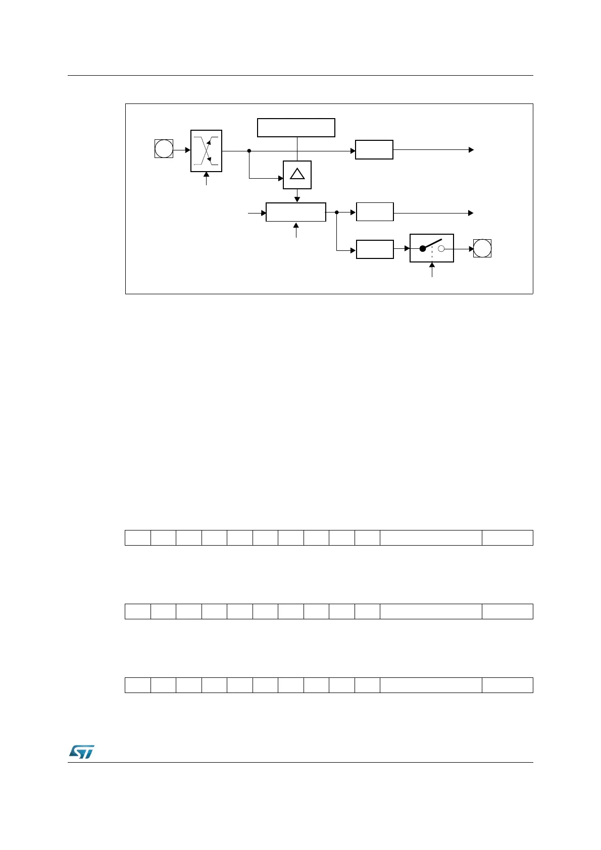
Figure 88. GPT1 auxiliary timer in capture mode
LUpon a trigger (selected transition) at the corresponding input pin TxIN the contents of the
core timer are loaded into the auxiliary timer register and the associated interrupt request
flag TxIR will be set.
Note: The direction control bit DP3.7 (for T2IN) and DP3.5 (for T4IN) must be set to '0', and the
level of the capture trigger signal should be held high or low for at least eight CPU clock
cycles before it changes to ensure correct edge detection.
9.1.3 Interrupt control for GPT1 timers
When a timer overflows from FFFFh to 0000h (when counting up), or when it underflows
from 0000h to FFFFh (when counting down), its interrupt request flag (T2IR, T3IR or T4IR)
in register TxIC will be set. This will cause an interrupt to the respective timer interrupt
vector (T2INT, T3INT or T4INT) or trigger a PEC service, if the respective interrupt enable
bit (T2IE, T3IE or T4IE in register TxIC) is set. There is an interrupt control register for each
of the three timers.
T2IC (FF60h / B0h) SFR Reset Value: - - 00h
T3IC (FF62h / B1h) SFR Reset Value: - - 00h
T4IC (FF64h / B2h) SFR Reset Value: - - 00h
Note: Details of the control fields is given in the general Interrupt Control Register description.
Txl
Capture Register Tx
TxIR
Interrupt
Request
Edge
Select
x = 2, 4
Core Timer T3
Up/Down
Input
Clock
T3IR
Interrupt
Request
T3OTL
T3OE
T3OUT
P3.3
TxIN
P3.7
P3.5
1514131211109876543210
--------T2IRT2IE ILVL GLVL
RW RW RW RW
1514131211109876543210
--------T3IRT3IE ILVL GLVL
RW RW RW RW
1514131211109876543210
--------T4IRT4IE ILVL GLVL
RW RW RW RW