Watchdog timer UM0404
300/564 DocID13284 Rev 2
The time period for an overflow of the watchdog timer is programmable in two ways:
• The input frequency to the watchdog timer can be selected via bit WDTIN in register
WDTCON to be either f
CPU
/2 or f
CPU
/128.
• The reload value WDTREL for the high byte of WDT can be programmed in register
WDTCON.
The period P
WDT
between servicing the watchdog timer and the next overflow can therefore
be determined by the following formula:
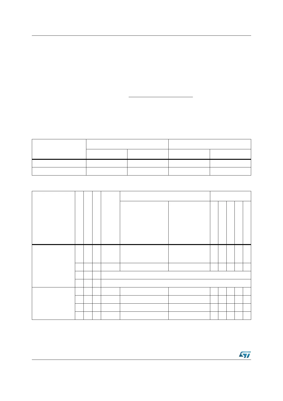
Refer to the device datasheet for a table of watchdog timer ranges. For security, you are
advised to rewrite WDTCON each time before the watchdog timer is serviced.
The
Table 43 shows the watchdog time range for 40 MHz and 64 MHz CPU clock.
P
WDT
=
f
CPU
2
[1 + (WDTIN) x 6]
x [2
16
- (WDTREL) x 2
8
]
Table 43. WDTREL reload value
Reload value in WDTREL
Prescaler for f
CPU
= 40 MHz Prescaler for f
CPU
= 64 MHz
2 (WDTIN = ‘0’) 128 (WDTIN = ‘1’) 2 (WDTIN = ‘0’) 128 (WDTIN = ‘1’)
FFh 12.8μs 819.2µs 8µs 512µs
00h 3.277ms 209.7ms 2.048ms 131.1ms
Table 44. Reset events summary
Event
RPD
EA
Bidir
Synch.
Asynch.
RSTIN WDTCON Flags
min max
PONR
LHWR
SHWR
SWR
WDTR
Power-on Reset
0 0 N Asynch.
1 ms (VREG)
1.2 ms (Reson. + PLL)
10.2 ms (Crystal + PLL)
- 11110
0 1 N Asynch. 1ms (VREG) - 1 1 1 1 0
1 x x Forbidden
x x Y Not applicable
Hardware reset
(Asynchronous)
0 0 N Asynch. 500ns - 0 1 1 1 0
0 1 N Asynch. 500ns - 0 1 1 1 0
0 0 Y Asynch. 500ns - 0 1 1 1 0
0 1 Y Asynch. 500ns - 0 1 1 1 0