Real time clock UM0404
466/564 DocID13284 Rev 2
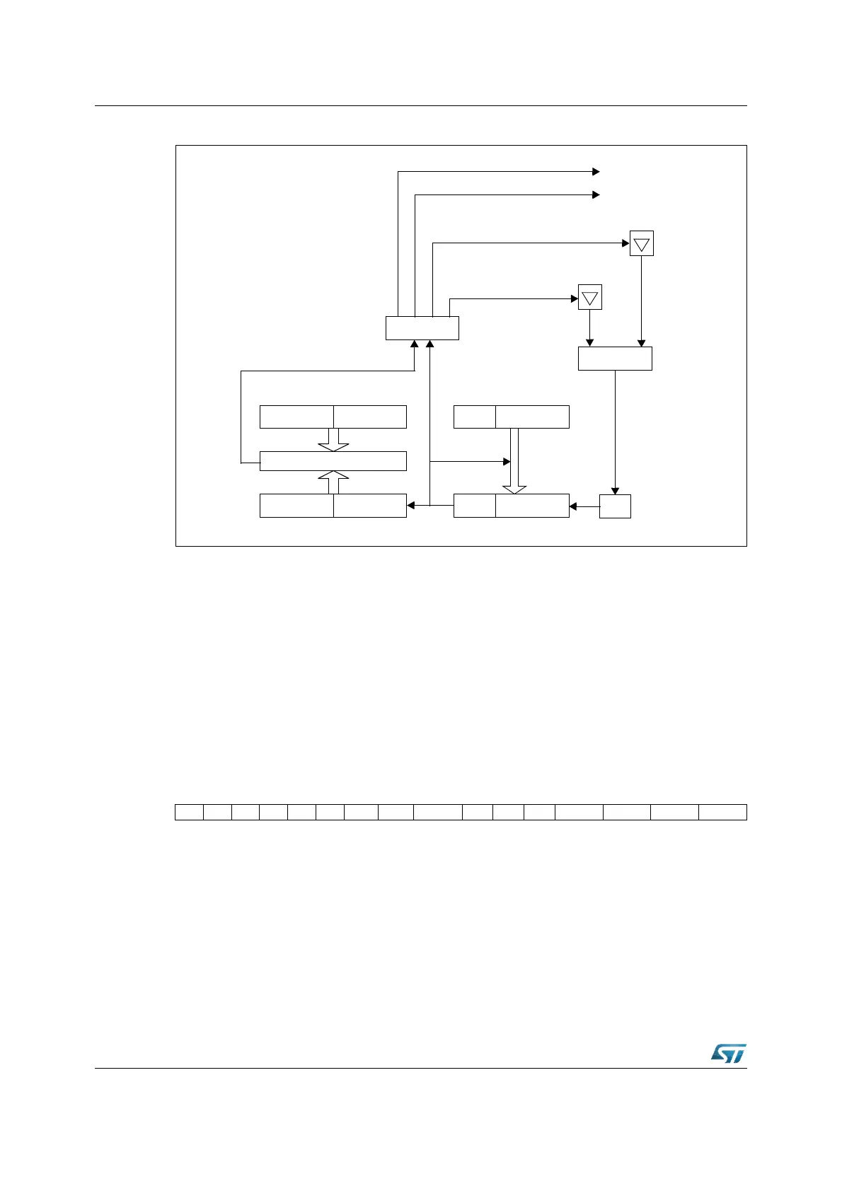
Figure 189. RTC block diagram
22.1 RTC registers
22.1.1 RTCCON: RTC control register
The functions of the RTC are controlled by the RTCCON control register. If the RTOFF bit is
set, the RTC dividers and counters clock is disabled and registers can be written, when the
ST10 chip enters Power Down mode the clock oscillator will be switch off. The RTC has two
interrupt sources, one is triggered every basic clock period, the other one is the alarm.
RTCCON includes an interrupt request flag and an interrupt enable bit for each of them.
This register is read and written via the XBUS.
RTCCON (ED00h) XBUS Reset Value: 0x00h
Reset Value: 0000 000x 0000 0000b
/64
RTCPLRTCPH
RTCDH RTCDL
RTCAH RTCAL
Main
Reload
=
programmable 20 bits divider32 bits Counter
RTCCON
Alarm IT
Basic Clock IT
RTCAI
RTCSI
MUX
OSC_STOP
OSC32_STOP
32 kHz Oscillator
Clock Oscillator
Programmable Alarm register Programmable Prescaler register
RTCH RTCL
1514131211109876543210
------OFF32OSC RTCOFF - - - RTCAEN RTCAIR RTCSEN RTCSIR
RWRRW RWRWRWRW