Parallel ports UM0404
138/564 DocID13284 Rev 2
Note: PICON is an ESFR register, while XPICON is an XBUS register. To access XPICON register
bit XMISCEN of register XPERCON and bit XPEN of register SYSCON must be set.
All options for individual direction and output mode control are available for each pin,
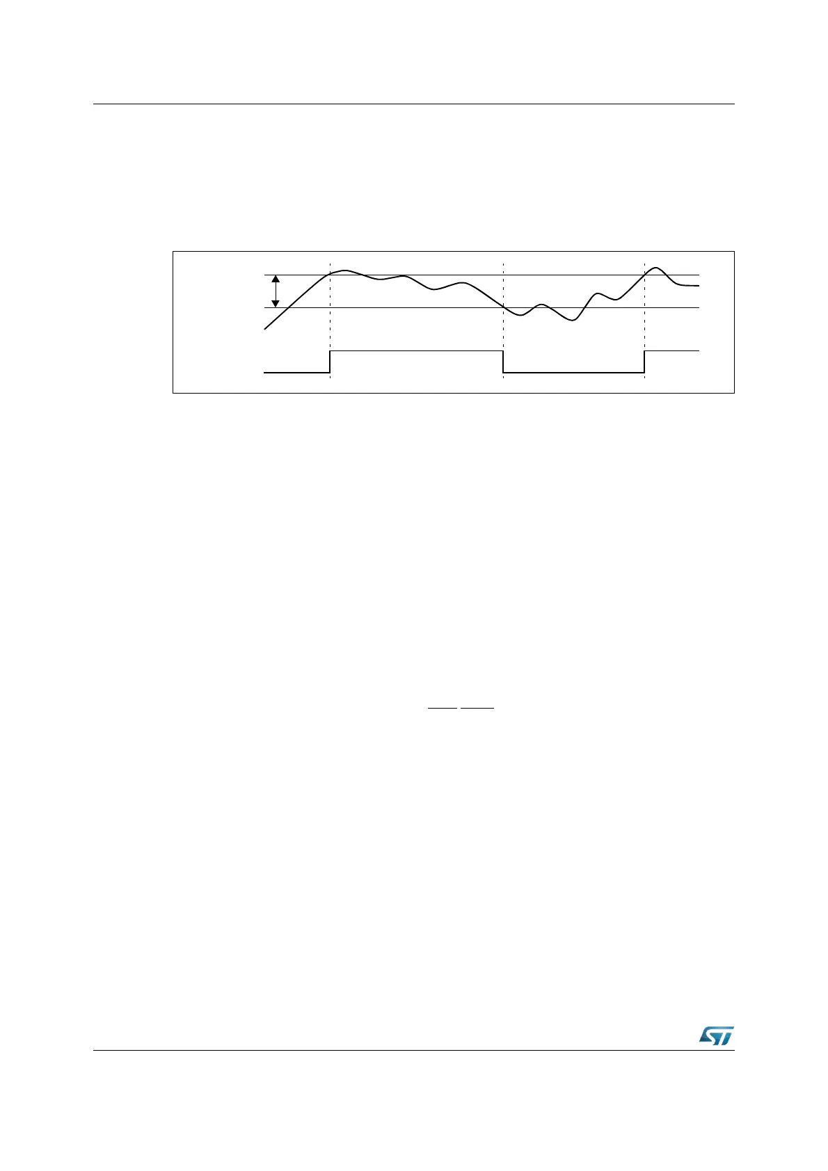
independent of the selected input threshold. The input hysteresis (different according to TTL
or CMOS selection) provides stable inputs from noisy or slowly changing external signals.
Figure 27. Hysteresis concept
6.1.3 Alternate port functions
Each port line has one or more associated programmable alternate input or output function.
PORT0 and PORT1 may be used as the address and data lines when accessing external
memory. Besides, PORT1 provides also Input Capture lines and additional (8) analog input
channels to the A/D Converter.
Port4 outputs the additional segment address bit A23...A16 in systems where more than
64 Kbytes of memory are to be accessed directly. In addition, CAN1, CAN2 and I
2
C lines
are provided.
Port6 provides the optional chip select outputs, the bus arbitration lines, and the XSSC
lines.
Port2, Port7 and Port8 are associated with the capture inputs or compare outputs of the
CAPCOM units and/or with the outputs of the PWM module, of the XPWM module and of
the XASC.
Port2 is also used for fast external interrupt inputs and for timer 7 input.
Port3 includes alternate input/output functions of timers, standard serial interfaces (SSC
and ASC), the optional bus control signal BHE
/WRH and the system clock output
(CLKOUT). Port5 is used for the analog input channels (16) to the A/D converter or timer
control signals.
If the alternate output function of a pin is to be used, the direction of this pin must be
programmed for output (DPx.y=‘1’), except for some signals that are used directly after reset
and are configured automatically. Otherwise the pin remains in the high-impedance state
and is not effected by the alternate output function. The respective port latch should hold a
‘1’, because its output is ANDed with the alternate output data (except for PWM output
signals).
If the alternate input function of a pin is used, the direction of the pin must be programmed
for input (DPx.y=‘0’) if an external device is driving the pin. The input direction is the default
after reset. If no external device is connected to the pin, however, one can also set the
direction for this pin to output. In this case, the pin reflects the state of the port output latch.
Thus, the alternate input function reads the value stored in the port output latch. This can be
used for testing purposes to allow a software trigger of an alternate input function by writing
to the port output latch.
Input level
Bit state
Hysteresis