DocID13284 Rev 2 137/564
UM0404 Parallel ports
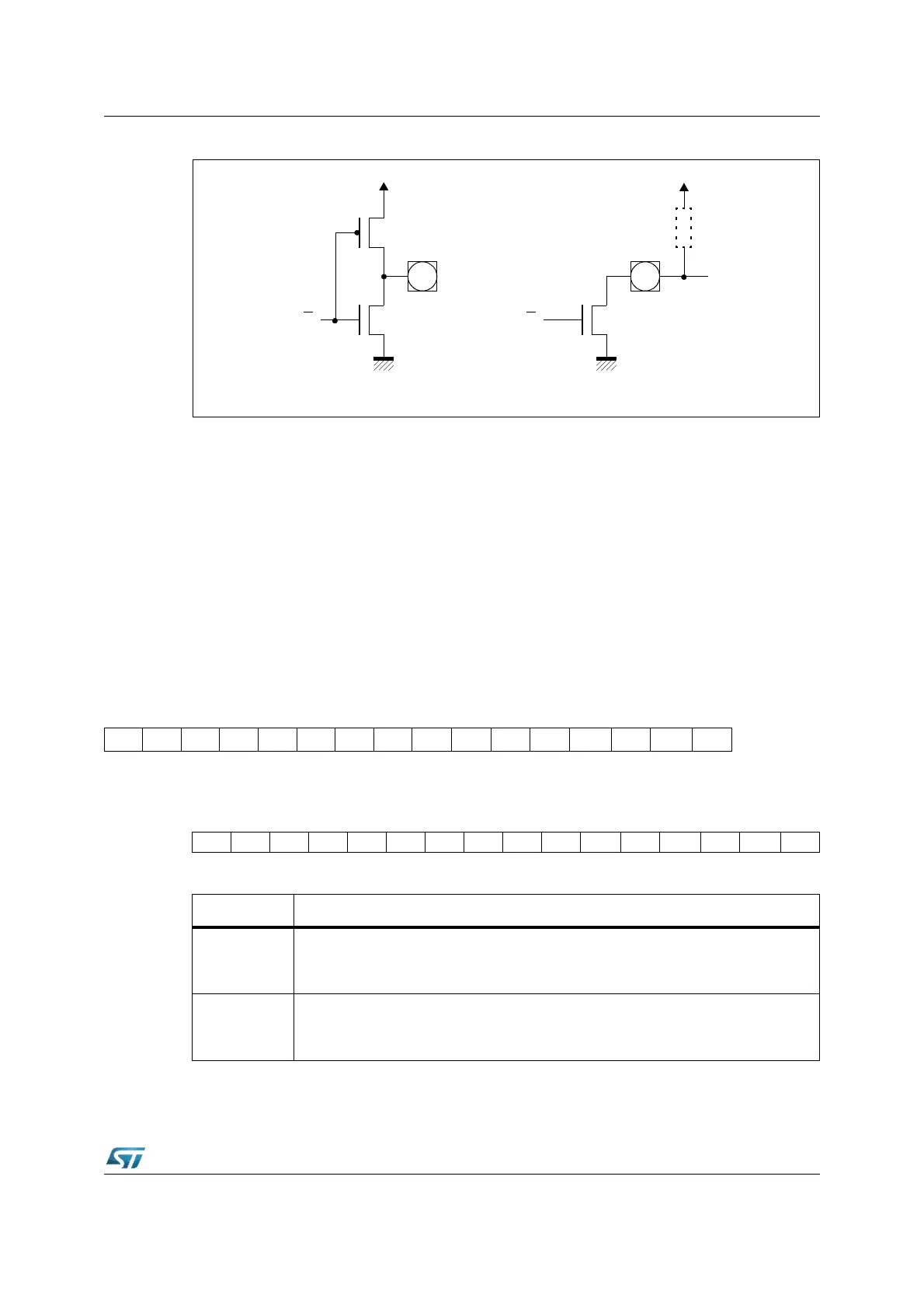
Figure 26. Output drivers in push-pull mode and in open drain mode
6.1.2 Input threshold control
The standard inputs of the ST10F276 determine the status of input signals according to TTL
levels.
In order to accept and recognize noisy signals, CMOS input thresholds can be selected
instead of the standard TTL thresholds for all pins of all Ports. These CMOS configuration
features also a higher hysteresis, to prevent the inputs from toggling while the respective
input signal level is near the thresholds.
Two Port Input Control registers (PICON and XPICON) are used to select these thresholds
for each byte of the indicated ports: the 8-bit ports P4, P6, P7 and P8 are controlled by one
bit each while ports P0, P1, P2, P3 and P5 are controlled by two bits each.
PICON (F1C4h / E2h) ESFR Reset Value: - - 00h
XPICON (EB26h) XBUS Reset Value: - - 00h
Q
Push-Pull Output Driver
Q
Open Drain Output Driver
External
Pull-up
15 14 13 12 11 10 9 8 7 6 5 4 3 2 1 0
- - - - - - - - P8LINP7LINP6LINP4LINP3HINP3LINP2HINP2LIN
RW RW RW RW RW RW RW RW
1514131211109876543210
----------P5HINP5LINP1HINP1LINP0HINP0LIN
RW RW RW RW RW RW
Bit Function
PxLIN
Port x Low Byte Input Level Selection
’0’: Pins Px.7...Px.0 switch on standard TTL input levels.
’1’: Pins Px.7...Px.0 switch on standard CMOS input levels.
PxHIN
Port x High Byte Input Level Selection
’0’: Pins Px.15...Px.8 switch on standard TTL input levels.
’1’: Pins Px.15...Px.8 switch on standard CMOS input levels.