The general purpose timer units UM0404
224/564 DocID13284 Rev 2
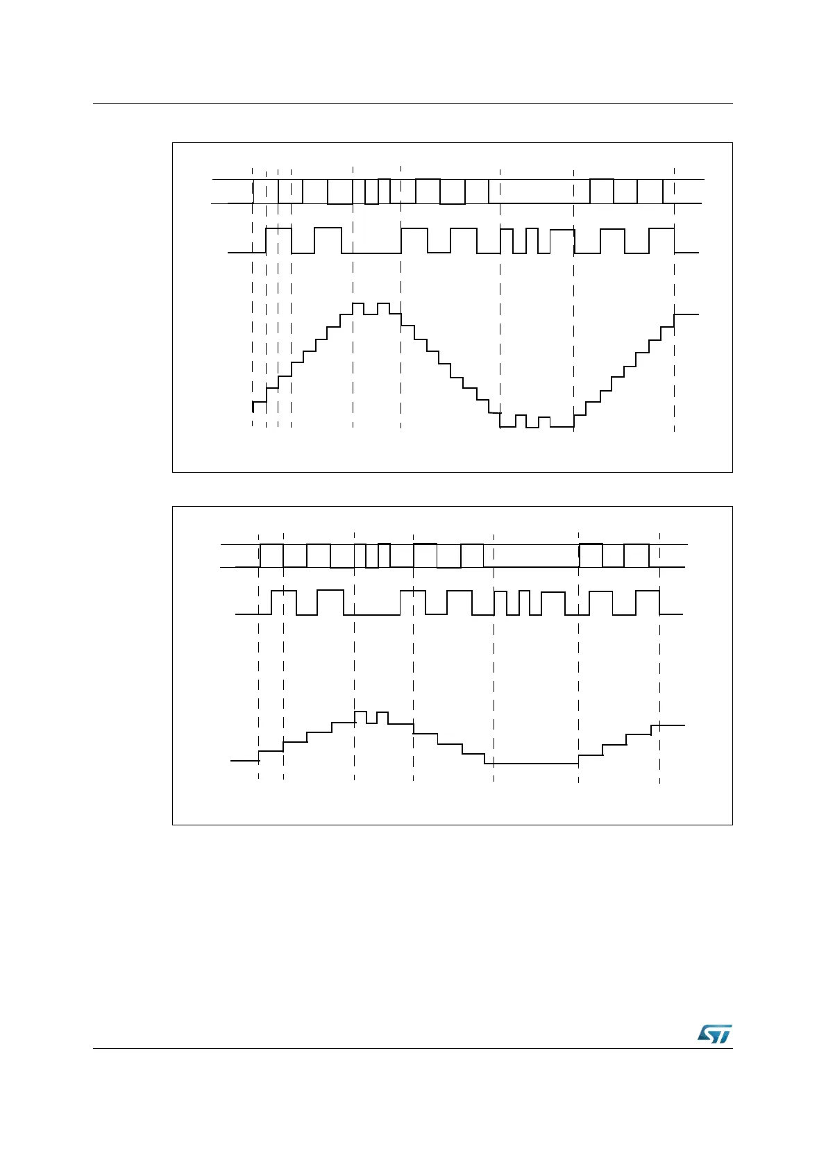
Figure 82. Evaluation of the incremental encoder signals
Figure 83. Evaluation of the incremental encoder signals
Note: Timer 3 operating in incremental interface mode automatically provides information on the
sensor’s current position. Dynamic information (speed, acceleration, deceleration) may be
obtained by measuring the incoming signal periods. This is facilitated by an additional
special capture mode for timer T5.
9.1.2 GPT1 auxiliary timers T2 and T4
Both auxiliary timers T2 and T4 have exactly the same functionality. They can be configured
like timer, gated timer, or counter mode with the same options for the timer frequencies and
the count signal as the core timer T3. In addition to these 3 counting modes, the auxiliary
forward jitter backward jitter forward
T3IN
T3EUD
Contents
of T3
up
down
up
Note: This example shows the timer behavior assuming that T3 counts upon any transition on any
input, T3I=’011b’
forward jitter backward jitter forward
T3IN
T3EUD
Contents
of T3
up
down
up
Note: This example shows the timer behavior assuming that T3 counts upon any transition on T3IN
input, T3I=’001b’