DocID13284 Rev 2 225/564
UM0404 The general purpose timer units
timers can be concatenated with the core timer, or they may be used as reload or capture
registers in conjunction with the core timer. The auxiliary timers have no output toggle latch
and no alternate output function.
The individual configuration for timers T2 and T4 is determined by their bit-addressable
control registers T2CON and T4CON, which are both organized identically.
Note that functions which are present in all three timers of block GPT1 are controlled in the
same bit positions and in the same manner in each of the specific control registers.
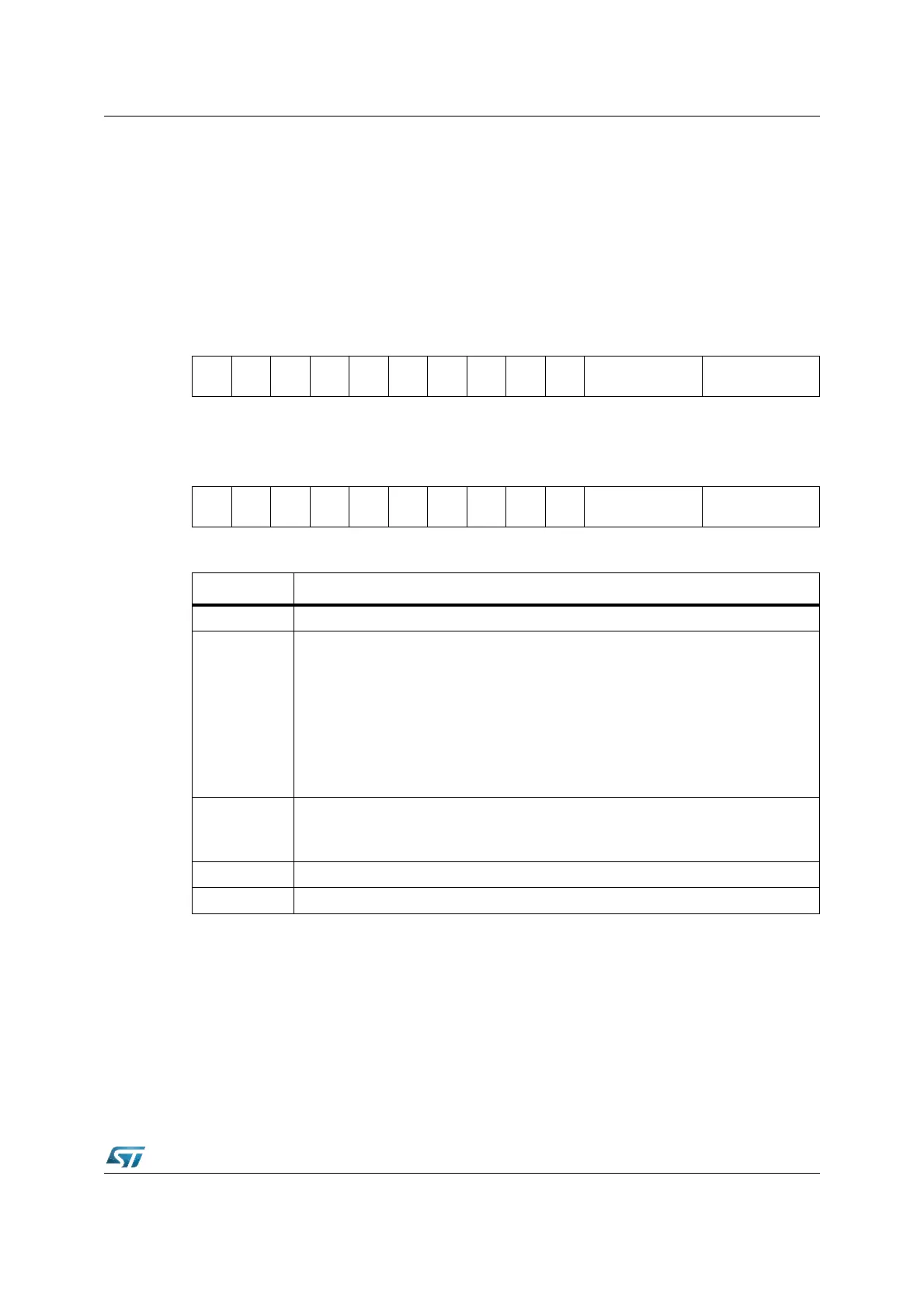
T2CON (FF40h / A0h) SFR Reset Value: 0000h
T4CON (FF44h / A2h) SFR Reset Value: 0000h
Count direction control for auxiliary timers
The count direction of the auxiliary timers can be controlled in the same way as for the core
timer T3. The description and the table apply accordingly.
Timers T2 and T4 in timer mode or gated timer mode
When the auxiliary timers T2 and T4 are programmed to timer mode or gated timer mode,
their operation is the same as described for the core timer T3. The descriptions, figures and
1514131211109876543210
-------
T2UD
E
T2UD T2R T2M T2I
RW RW RW RW RW
1514131211109876543210
-------
T4UD
E
T4UD T4R T4M T4I
RW RW RW RW RW
Bit Function
TxI Timer x Input Selection Depends on the Operating Mode, see respective sections.
TxM
Timer x Mode Control (Basic Operating Mode)
0 0 0: Timer Mode
0 0 1: Counter Mode
0 1 0: Gated Timer with Gate active low
0 1 1: Gated Timer with Gate active high
1 0 0: Reload Mode
1 0 1: Capture Mode
1 1 0: Incremental interface mode
1 1 1: Reserved (do not use this combination)
TxR
Timer x Run bit
TxR = ‘0’: Timer / Counter x stops
TxR = ‘1’: Timer / Counter x runs
TxUD Timer x Up / Down Control
(1)
1. For the effects of bit TxUD and TxUDE refer to the direction Table 35 in T3 section.
TxUDE Timer x External Up/Down Enable
(1)