DocID13284 Rev 2 413/564
UM0404 CAN modules
21.2 Interrupt
Up to four interrupt control registers (XIRxSEL, x = 0, 1, 2, 3) are provided in order to select
the source of the XBUS interrupt: one line for each module is provided and differently linked
to one of the XPxIC registers (x = 0, 1, 2, 3). In particular, the two interrupt lines are
available on the following interrupt vectors:
• CAN1 XP0INT XP3INT
• CAN2 XP1INT XP3INT
Refer to Section 5.7: X-peripheral interrupt on page 117 for details.
When interruptible Power Down mode is entered, both CAN1 and CAN2 lines can be used
to wake-up the device from low power mode without resetting it, restarting the application
from where it was stopped before the execution of PWRDN instruction.
Refer to Section 5.6.1: Fast external interrupts on page 115.
21.3 Configuration support
It is possible that both CAN controllers are working on the same CAN bus, supporting
together up to 64 message objects. In this configuration, both receive signals and both
transmit signals are linked together when using the same CAN transceiver. This
configuration is especially supported by providing open drain outputs for the CAN1_Txd and
CAN2_TxD signals. The open drain function is controlled with the ODP4 register for port P4:
in this way it is possible to connect together P4.4 with P4.5 (receive lines) and P4.6 with
P4.7 (transmit lines to be configured as Open-Drain).
The user is also allowed to map internally both CAN modules on the same pins P4.5 and
P4.6. In this way, P4.4 and P4.7 may be used either as general purpose I/O lines, or used
for I
2
C interface. This is possible by setting bit CANPAR of XMISC register. To access this
register it is necessary to set bit XMISCEN of XPERCON register and bit XPEN of SYSCON
register.
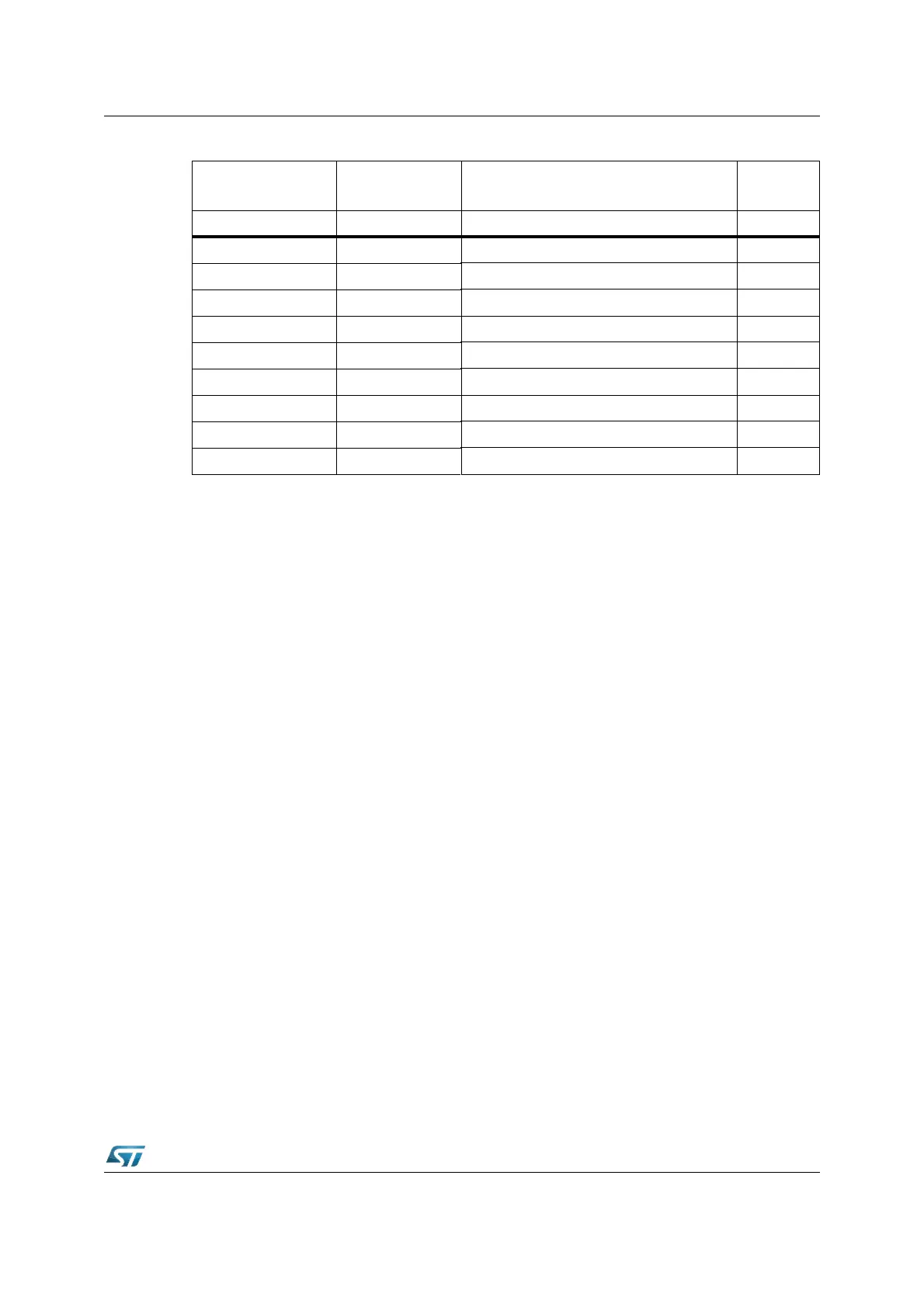
CAN2IF2DB1 EE52h CAN2: IF2 Data B 1 0000h
CAN2IF2DB2 EE54h CAN2: IF2 Data B 2 0000h
CAN2TR1 EE80h CAN2: Transmission Request 1 0000h
CAN2TR2 EE82h CAN2: Transmission Request 2 0000h
CAN2ND1 EE90h CAN2: New Data 1 0000h
CAN2ND2 EE92h CAN2: New Data 2 0000h
CAN2IP1 EEA0h CAN2: Interrupt Pending 1 0000h
CAN2IP2 EEA2h CAN2: Interrupt Pending 2 0000h
CAN2MV1 EEB0h CAN2: Message Valid 1 0000h
CAN2MV2 EEB2h CAN2: Message Valid 2 0000h
Table 59. CAN2 register mapping
Name Physical address Description
Reset
value