DocID13284 Rev 2 221/564
UM0404 The general purpose timer units
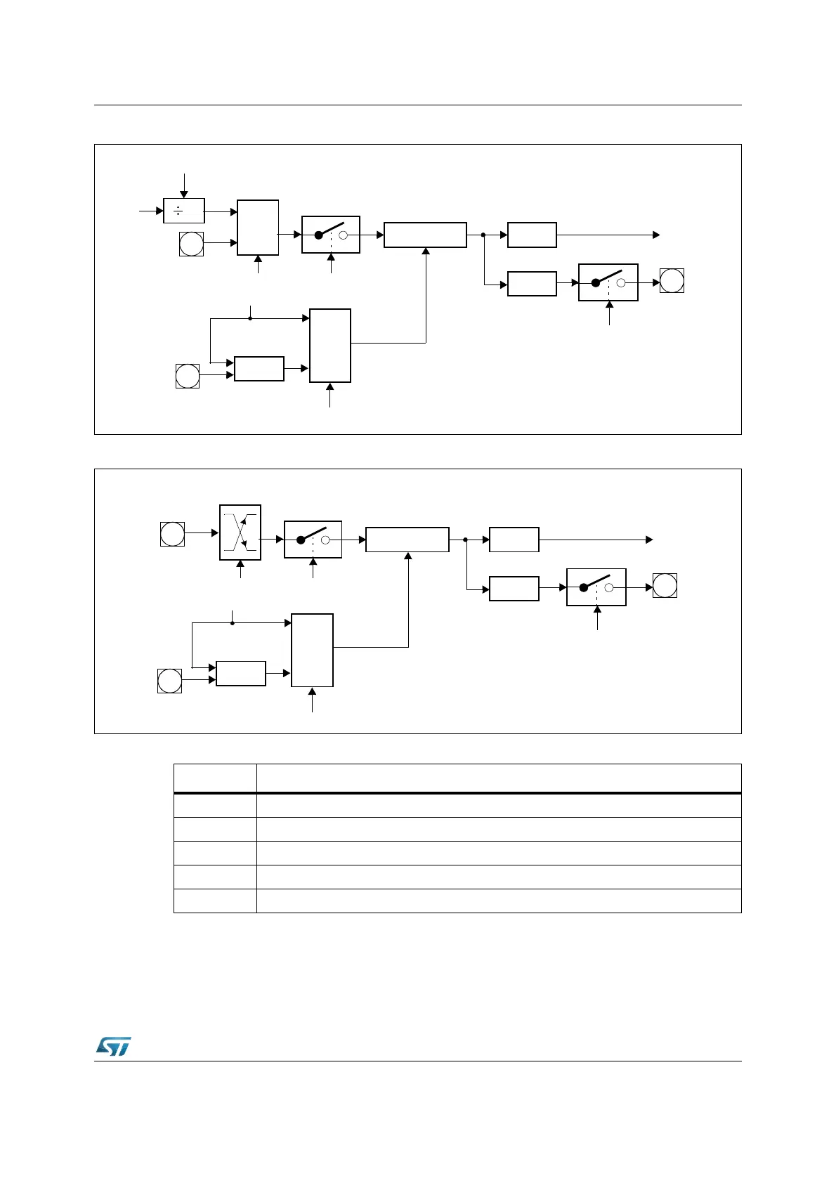
Figure 78. Core timer T3 in gated timer mode
Figure 79. Core timer T3 in counter mode
For counter operation, pin T3IN/P3.6 must be configured as input, and direction control bit
DP3.6 must be ‘0’. The maximum input frequency, allowed in counter mode, is f
CPU
/ 16.
X
T3l
CPU
Clock
T3R
MUX
T3UDE
Core Timer T3
T3IR
Interrupt
Request
T3OTL
T3OE
T3OUT
Up/Down
XOR
1
0
T3UD
T3EUD
T3M
T3IN
P3.3
P3.4
P3.6
T3l
T3R
MUX
T3UDE
Core Timer T3
T3IR
Interrupt
Request
T3OTL
T3OE
T3OUT
Up/Down
XOR
1
0
T3UD
T3EUD
T3IN
Edge
Select
P3.6
P3.4
P3.3
Table 35. GPT1 core timer T3 (counter mode) input edge selection
T3I Triggering edge for counter increment / decrement
0 0 0 None. Counter T3 is disabled
0 0 1 Positive transition (rising edge) on T3IN
0 1 0 Negative transition (falling edge) on T3IN
0 1 1 Any transition (rising or falling edge) on T3IN
1 X X Reserved. Do not use this combination