Asynchronous / synchronous serial interface UM0404
250/564 DocID13284 Rev 2
modulo-2-sum of the 7 data bits is ‘1’. An odd parity bit will be cleared in this case. Parity
checking is enabled via bit S0PEN (always OFF in 8-bit data mode). The parity error flag
S0PE will be set along with the error interrupt request flag, if a wrong parity bit is received.
The parity bit itself will be stored in bit S0RBUF.7.
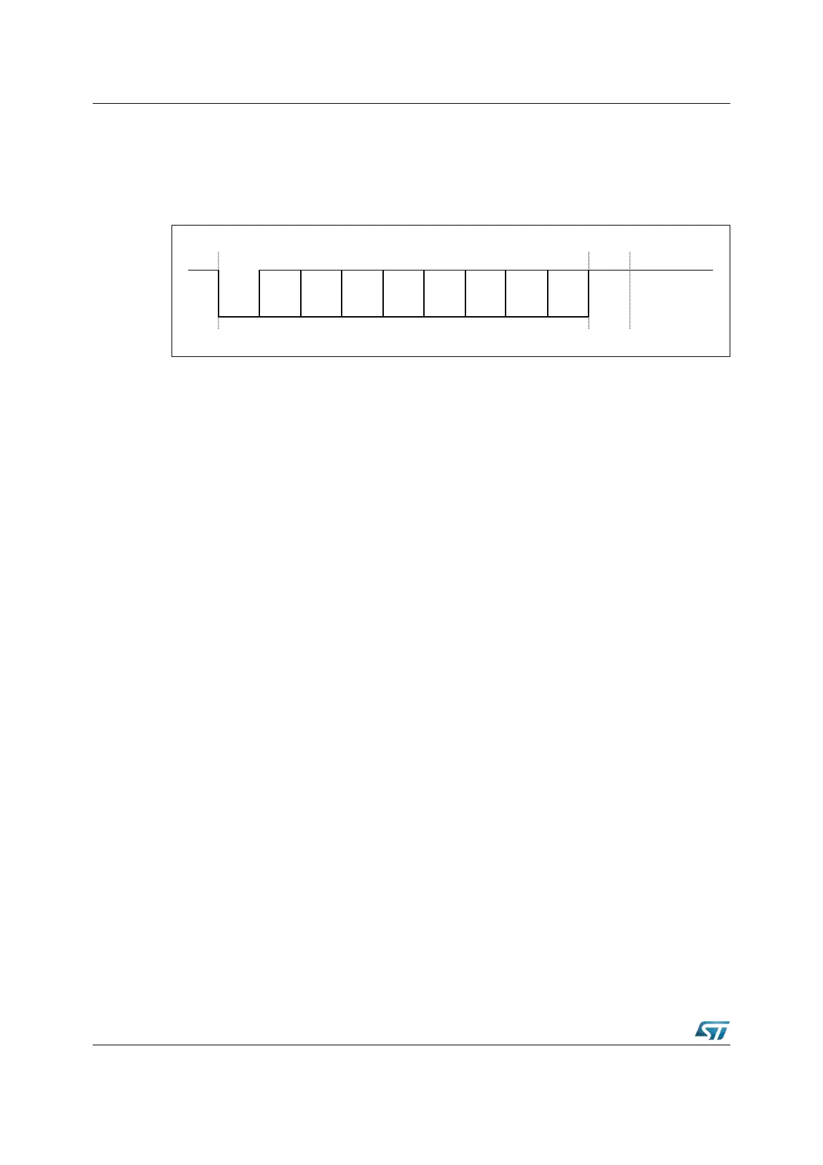
Figure 101. Asynchronous 8-bit data frames
9-bit data frames either consist of 9 data bits D8...D0 (S0M = ‘100b’), of 8 data bits D7...D0
plus an automatically generated parity bit (S0M = ‘111b’) or of 8 data bits D7...D0 plus wake-
up bit (S0M = ‘101b’). Parity may be odd or even, depending on bit S0ODD in register
S0CON. An even parity bit will be set, if the modulo-2-sum of the 8 data bits is ‘1’. An odd
parity bit will be cleared in this case. Parity checking is enabled via bit S0PEN (always OFF
in 9-bit data and wake-up mode). The parity error flag S0PE will be set along with the error
interrupt request flag, if a wrong parity bit is received. The parity bit itself will be stored in bit
8 of S0RBUF.
In wake-up mode received frames are only transferred to the receive buffer register, if the
9th bit (the wake-up bit) is ‘1’. If this bit is ‘0’, no receive interrupt request will be activated
and no data will be transferred.
This feature may be used to control communication in multi-processor system when the
master processor wants to transmit a block of data to one of several slaves, it first sends out
an address byte which identifies the target slave. An address byte differs from a data byte in
that the additional 9th bit is a '1' for an address byte and a '0' for a data byte, so no slave will
be interrupted by a data byte. An address byte will interrupt all slaves (operating in 8-bit data
+ wake-up bit mode), so each slave can examine the 8 LSBs of the received character (the
address).
The addressed slave will switch to 9-bit data mode (by clearing bit S0M.0), which enables it
to also receive the data byte that will be coming (having the wake-up bit cleared). The
slaves that were not being addressed remain in 8-bit data + wake-up bit mode, ignoring the
following data byte (see Figure 102).
Asynchronous transmission begins at the next overflow of the divide-by-16 counter (see
Figure 102), provided that S0R is set and data has been loaded into S0TBUF. The
transmitted data frame consists of three basic elements:
• the start bit,
• the data field (8 or 9 bits, LSB first, including a parity bit, if selected),
• the delimiter (1 or 2 stop bits).
Data transmission is double buffered. When the transmitter is idle, the transmit data loaded
into S0TBUF is immediately moved to the transmit shift register thus freeing S0TBUF for the
next data to be sent. This is indicated by the transmit buffer interrupt request flag S0TBIR
being set. S0TBUF may now be loaded with the next data, while transmission of the
previous one is still going on.
2nd
Stop
bit
Start
bit
D0
(LSB)
D1 D2 D3 D4 D5 D6 D7 /
Parity
(1st)
Stop
Bit