High-speed synchronous serial interface UM0404
282/564 DocID13284 Rev 2
that slaves not selected for transmission only shift out ones, so their transmit buffers must
be loaded with 'FFFFh' prior to any transfer.
Note: A slave with push-pull output drivers, which is not selected for transmission, will normally
have its output drivers switched. However, in order to avoid possible conflicts or
misinterpretations, it is recommended to always load the slave's transmit buffer prior to any
transfer (see Figure 116).
12.5 SSC interrupt control
Three interrupt control registers are provided for serial channel SSC. Register SSCTIC
controls the transmit interrupt, SSCRIC controls the receive interrupt and SSCEIC controls
the error interrupt of serial channel SSC. Each interrupt source also has its own dedicated
interrupt vector. SCTINT is the transmit interrupt vector, SCRINT is the receive interrupt
vector, and SCEINT is the error interrupt vector.
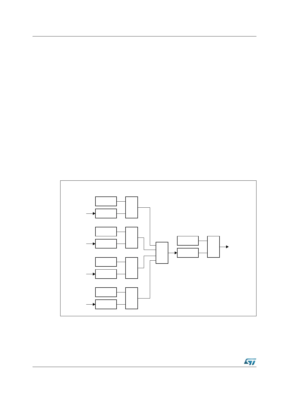
The cause of an error interrupt request (receive, phase, Baud rate, transmit error) can be
identified by the error status flags in control register SSCCON.
Note: In contrary to the error interrupt request flag SSCEIR, the error status flags SSCxE are not
reset automatically upon entry into the error interrupt service routine, but must be cleared by
software.
Figure 116. SSC error interrupt control
SSCTE
Register SSCCON
SSCTE
&
Transmit
Error
SSCRE
SSCRE
&
Receive
Error
SSCPE
SSCPE
&
SSCBE
SSCBE
&
Phase
Error
Baudrate
Error
≥ 1
SSCEIE
SSCEIR
&
Error
Interrupt
SSCEINT
Register SSCEIR