Parallel ports UM0404
170/564 DocID13284 Rev 2
The lower four lines of Port7 (P7.3...P7.0) supports outputs of the PWM module
(POUT3...POUT0). At these pins the value of the respective port output latch is XORed with
the value of the PWM output rather than ANDed, as the other pins do. This allows to use the
alternate output value either as it is (port latch holds a ‘0’) or invert its level at the pin (port
latch holds a ‘1’).
Note that the PWM outputs must be enabled via the respective PENx bit in PWMCON1.
The Table 27 summarizes the alternate functions of Port7.
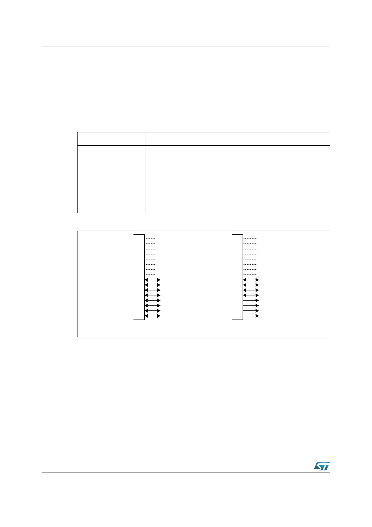
Figure 49. Port7 I/O and alternate functions
The structure of Port7 differs in the way the output latches are connected to the internal bus
and to the pin driver (see Figure 2 on page 24 and Figure 3 on page 30).
Pins P7.3...P7.0 (POUT3...POUT0) XOR the alternate data output with the port latch output,
which allows to use the alternate data directly or inverted at the pin driver.
Table 27. Port7 alternate functions
Port7 pin Alternate function
P7.0
P7.1
P7.2
P7.3
P7.4
P7.5
P7.6
P7.7
POUT0 PWM mode channel 0 output
POUT1 PWM mode channel 1 output
POUT2 PWM mode channel 2 output
POUT3 PWM mode channel 3 output
CC28 I/O Capture input / compare output channel 28
CC29 I/O Capture input / compare output channel 29
CC30 I/O Capture input / compare output channel 30
CC31 I/O Capture input / compare output channel 31
Port7
-
-
-
-
-
-
-
-
CC31IO
CC30IO
CC29IO
CC28IO
POUT3
POUT2
POUT1
POUT0
Alternate Function
General Purpose
Input/Output
-
-
-
-
-
-
-
-
P7.7
P7.6
P7.5
P7.4
P7.3
P7.2
P7.1
P7.0