CAN modules UM0404
416/564 DocID13284 Rev 2
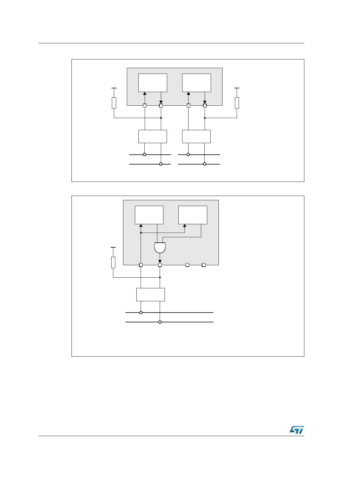
Figure 174. Connection to two different CAN buses (e.g. for gateway application)
Figure 175. Connection to one CAN bus with internal parallel mode enabled
21.4 Clock Prescaling
In the register XMISC there is also a bit (CANCK2) to modify the clock frequency driving
both the CAN modules. For architectural limitations of the CAN module, when the CPU
frequency is higher than 40 MHz, it is recommended to provide the CPU clock divided by 2
to each CAN module. 20 MHz is sufficient for CAN module to produce the maximum
CAN_H
CAN_L
CAN bus 1
CAN_H
CAN_L
CAN bus 2
XMISC.CANPAR = 0
CAN CAN
TransceiverTransceiver
CAN1
RX TX
CAN2
RX TX
P4.4 P4.7P4.5 P4.6
+5V
2.7kΩ
+5V
2.7kΩ
XMISC.CANPAR = 1
CAN2
RX TX
P4.4 P4.7P4.5 P4.6
CAN
CAN_H
CAN_L
CAN bus
Transceiver
CAN1
RX TX
(Both CAN enabled)
+5V
2.7kΩ
Note: P4.4 and P4.7 when not used as CAN functions can be used as general
purpose I/O while they cannot be used as external bus address lines.
Refer to Section 6.6.1: Alternate functions of Port4 for more details.