The general purpose timer units UM0404
220/564 DocID13284 Rev 2
The timer resolutions which result from the selected pre-scaler option are listed in the
Table 34. This table also applies to the Gated Timer Mode of T3 and to the auxiliary timers T2
and T4 in timer and gated timer mode.
Refer to the device datasheet for a table of timer input frequencies, resolution and periods
for the range of pre-scaler options.
Timer 3 in gated timer mode
Gated timer mode for the core timer T3 is selected by setting bit-field T3M in register
T3CON to ‘010b’ or ‘011b’. Bit T3M.0 (T3CON.3) selects the active level of the gate input. In
gated timer mode the same options for the input frequency as for the timer mode are
available.
However, the input clock to the timer in this mode is gated by the external input pin T3IN
(Timer T3 External Input), which is an alternate function of P3.6. To enable this operation pin
T3IN/P3.6 must be configured as input, and direction control bit DP3.6 must contain ‘0’ (see
Figure 78). If T3M.0 = ‘0’, the timer is enabled when T3IN shows a low level. A high level at
this pin stops the timer. If T3M.0 = ‘1’, pin T3IN must have a high level in order to enable the
timer. In addition, the timer can be turned on or off by software using bit T3R. The timer will
only run, if T3R = ‘1’ and the gate is active. It will stop, if either T3R = ‘0’ or the gate is
inactive.
Note: A transition of the gate signal at pin T3IN does not cause an interrupt request.
Timer 3 in counter mode
Counter mode for the core timer T3 is selected by setting bit-field T3M in register T3CON to
‘001b’. In counter mode timer T3 is clocked by a transition at the external input pin T3IN,
which is an alternate function of P3.6.
The event causing an increment or decrement of the timer can be a positive, a negative, or
both a positive and a negative transition at this pin. Bit-field T3I in control register T3CON
selects the triggering transition (see
Table 35).
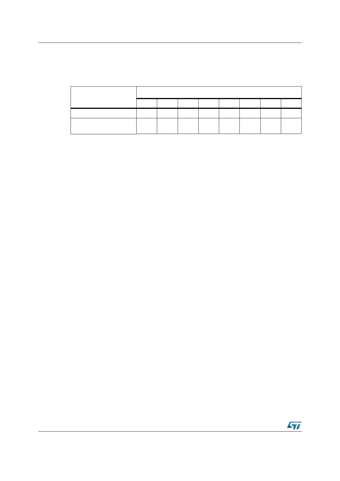
Table 34. GPT1 timer resolutions
Timer Input Selection T2I / T3I / T4I
000b 001b 010b 011b 100b 101b 110b 111b
Pre-scaler factor 8 16 32 64 128 256 512 1024
Resolution in CPU clock
cycles
8 16 32 64 128 256 512 1024