DocID13284 Rev 2 329/564
UM0404 The capture / compare units
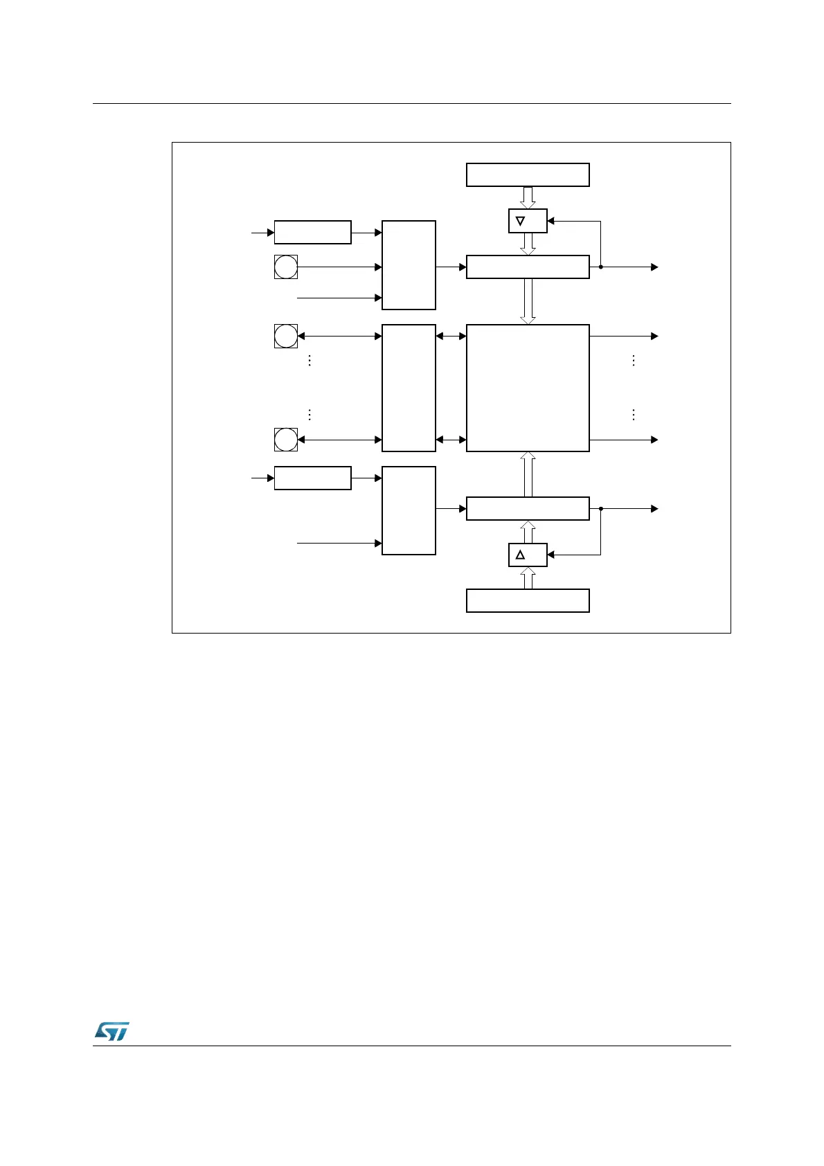
Figure 134. CAPCOM unit block diagram
Note: The CAPCOM2 unit provides 16 capture inputs, but only 12 compare outputs.
16.1 CAPCOM timers
The primary use of the timers T0 / T1 and T7 / T8 is to provide two independent time bases
for the capture / compare registers of each unit, but they may also be used independent of
the capture / compare registers. The basic structure of the four timers is identical, while the
selection of input signals is different for timers T0 / T7 and timers T1 / T8.
Tx
Input
Control
2
n
n = 3...10
GPT2 Timer T6
TxIN
CPU
Clock
Mode
Control
(Capture
or
Compare)
16
Capture inputs
Compare outputs
Ty
Input
Control
2
n
n = 3...10
GPT2 Timer T6
Over / Underflow
CPU
Clock
Reload Register TxREL
CAPCOM Timer Tx
Interrupt
Request
Sixteen 16-bit
(Capture/Compare)
Registers
Over / Underflow
CAPCOM Timer Ty
Reload Register TyREL
16
Capture / Compare
Interrupt Requests
Interrupt
Request
x = 0, 7
y = 1, 8