The external bus interface UM0404
214/564 DocID13284 Rev 2
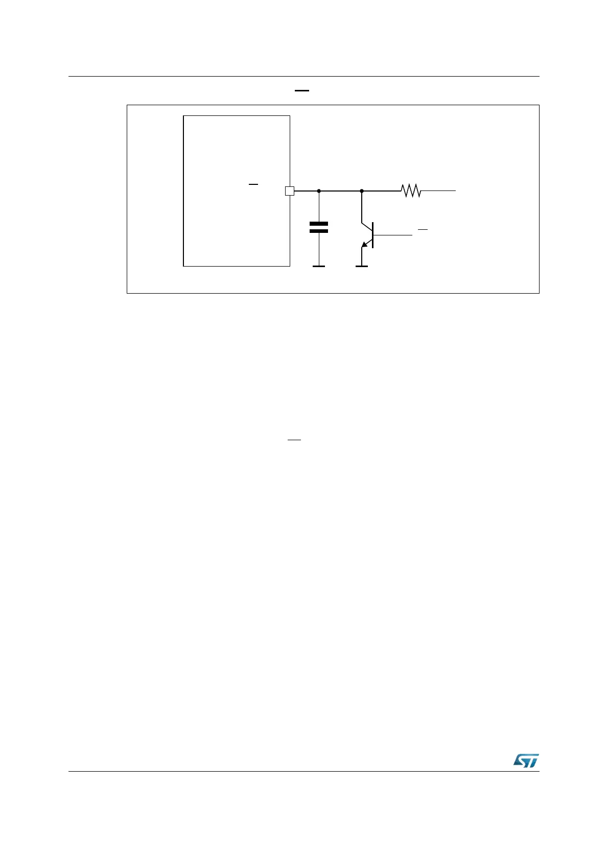
Figure 74. EA / V
STBY
external circuit
In Figure 74 the diagram of a possible external circuit is reported. Attention should be paid
in implementing the resistance for current limitation of bipolar: the same resistance should
not disturb the Stand-by mode when some current (in the order of hundreds of µA) is
provided to the device by the V
STBY
voltage supply source: the voltage at the pin of
ST10F276 should not become lower than 4.5 volt (4.0V when RTC and 32 kHz on-chip
oscillator amplifier are turned off).
In order to reduce the effect of the current consumption transients on V
STBY
pin (refer to
I
SB3
in the Electrical Characteristics section of datasheet) it is suggested to add an external
capacitance which can filter the eventual current peaks, which could create potential
problems of voltage drops in case a very low power external voltage regulator is used.
Additional care must be paid on external hardware to limit the current peaks due to the
presence of the capacitance (when EA
functionality is used and the external bipolar is
turned on, see Figure 74).
V
STBY
V
SS
4 - 5.5 Volt
EA
function
EA
/ V
STBY
ST10F276
V
SS